|
March 1, 2020 06:13:19
Posted By Kepler Lam
|
Just delivery the SIMOS class remotely, haven't been writing any blog entry for a long time, as its a very hard time in here. After almost half years of social campaign, its now still under the risk of coronavirus. Hopefully people in Hong Kong has the experience of SAS virus before, thus wearing mask everyday, and most likely it lower the chance of being infected.
Anyway, back to this bog entry which I want to compare the traditional DMVPN with the FlexVPN using the NHRP.
Although the functionsseems almost the same, both support the full mesh VPN tunnels. Both use static tunnel between the hub and all spokes sites, then establish dynamic tunnel between spokes sites on demand. The major different is the way how the spoke site learn the tunnel IP address of the other spoke site.
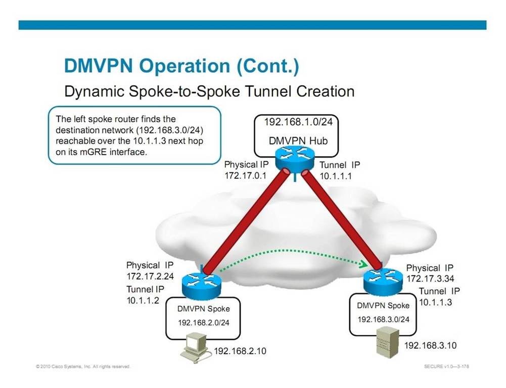
In the traditional DMVPN, the next hop address to the internal subnet of the other remote spoke site requires to be tunnel IP address of the remote spoke site.
E.g. in the following, the left spoke router finds the destination network (192.168.13.024) reachable over the 10.1.1.3 next hop on its mGRE interface.

In order to satisfy this requirement, you need to be care about the routing configuration.
For OSPF, you need to use the OSPF broadcast mode under the mGRE interface of all the spoke sites. If you use the default point-to-multipoint mode, the learnt next hop will become the hub's IP and simply won't work. Please refer to my other blog entry on OSPF mode in DMVPN configuration.
Similarly, for EIGRP, you need to disable the "next-hop-self" in the hub site's mGRE interface.
For the FlexVPN, you don't need to rely on the routing protocol to advertise the correct next hop. Instead, the hub site can advertise a default route to all spokes using the IKEv2 mode configure. So that, all spoke site will have a default route pointing to hub site.
Then what happen for spoke-to-spoke site traffic? Initially, the spoke will send the packet to the hub using the default route. But then the hub finds that the traffic can directly reach the other spoke using the remote spoke's tunnel IP, the hub will send a NHRP redirect (somewhat like the ICMP redirect) to the original spoke site, so that the original spoke will response a HNRP request to resolve the physical IP address of the remote site in order to establish the dynamic tunnel.
Following diagram illustrate the process:

Wish the above explains. Finally, may the God bless the the world to control the Wuhan virus.
|
|
April 12, 2014 11:14:34
Posted By Kepler Lam
|
In the discussion of the SECURE course 2 weeks ago, there is a topic about the routing options for DMVPN network. It mentions that If you are using full mesh mode for DMVPN, and using OSPF routing protocol, then you should use OSPF broadcast mode instead of point-to-multipoint mode for the tunnel interface.
The reason is that in DMVPN, spoke site to spoke site tunnel establishment relies on the next hop address to be the spoke site instead of the hub site, see the diagram below:
While OSPF broadcast mode satisfies this requirement, see my blog entry on OSPF broadcast and NBMA mode.
Author: Kepler Lam
Certified Cisco System Instructor since 1998
|
|
April 12, 2014 09:52:08
Posted By Kepler Lam
|
Again, I’m teaching Route course this week. Another things that students are interesting to discuss is about the compatibility of different OSPF mode in NBMA network.
I’m not going to discuss how those different mode are being used, as its been discussed in many other website. Those modes are summarized as the following slide:

If you take a look on the above summarized slide, you will find that there are 2 categories: one has DR/BDR selection (for the Broadcast and NBMA mode), while the other category does not have DR/BDR selection (other 3 modes). Actually, that is the boundary of compatibility i.e. the modes in same category are compatible.
Yet, maybe you also know that in order to form neighbors, OSPF routers will require to have consistence hello/dead interval. So even though the modes are compatible, you still need to make sure that the hello/dead interval need to be the same.
Besides, also depending on whether you are using main interface/multipoint/point-2-point subinterfaces, they have different default OSPF mode.
E.g. if you have a hub-and-spoke topology, your hub site uses a multipoint or main interface (which default mode is NBMA). Then for hub site to use OSPF point-2-multipoint mode, you need to explicitly configure. While for the spoke site, even it only has one single PVC to the hub, if you use the main interface instead of a point-2-point subinterface, you still need to define the mode in the main interface as point-2-point mode.
Following is a workable example:
Hub site:
hostname R1
!
interface Loopback0
ip address 10.1.1.1 255.255.255.255
!
interface Serial0/0/0
no ip address
encapsulation frame-relay
!
interface Serial0/0/0.1 multipoint
description Link to R2, R4
ip address 10.1.110.1 255.255.255.0
ip ospf network point-to-multipoint
frame-relay map ip 10.1.110.2 112 broadcast
frame-relay map ip 10.1.110.4 114 broadcast
!
router ospf 1
router-id 1.1.1.1
log-adjacency-changes
network 10.0.0.0 0.255.255.255 area 0
!
Spoke site:
hostname R2
!
interface Loopback0
ip address 10.2.2.2 255.255.255.255
!
interface Serial0/0/0
ip address 10.1.110.2 255.255.255.0
ip ospf network point-to-point
ip ospf hello-interval 30
encapsulation frame-relay
!
router ospf 1
router-id 2.2.2.2
log-adjacency-changes
network 10.0.0.0 0.255.255.255 area 0
!
R1 and R2 can successfully form neighbors and exchange routes:
R1#sh ip ospf neighbor
Neighbor ID Pri State Dead Time Address Interface
2.2.2.2 1 FULL/BDR 00:00:38 10.1.110.2 Serial0/0/0.1
R1#sh ip route
...
10.0.0.0/8 is variably subnetted, 3 subnets, 2 masks
O 10.2.2.2/32 [110/65] via 10.1.110.2, 00:02:49, Serial0/0/0.1
C 10.1.1.1/32 is directly connected, Loopback0
C 10.1.110.0/24 is directly connected, Serial0/0/0.1
Please visit my other blog entry for an exmaple of broadcast and NBMA mode.
|
|
April 12, 2014 09:52:08
Posted By Kepler Lam
|
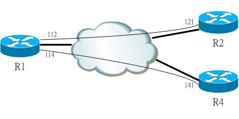
Although, OSPF broadcast and NMBA mode can also work in a partial mesh network, you need to carefully configure to make it works. There are few things that you need to cater:
- You need to select a site with all PVCs to all other site (e.g. hut site in a hut-and-spoke topology) as the DR and properly tune the priority.
- All sites still need to be directly reachable with each other, so if 2 sites that doesn’t have a PVC between them, then you need to explicitly use a frame-relay map to map the other sites through a PVC to a 3rd site that connects these 2 sites. E.g. spoke sites can reach each other through the hub site. (See the similar discussion for EIGRP NBMA design).
- Sites that use frame-relay map command to reach other site cannot use the broadcast mode, must use NBMA mode and explicitly define other sites as neighbors.
Following is a workable configuration where R1 is the hub site, R2 and R4 are 2 spoke sites that each only has one single PVC to R1.
R1:
interface Serial0/0/0.1 multipoint
description Link to R2, R4
ip address 10.1.110.1 255.255.255.0
ip ospf network broadcast
ip ospf priority 10
frame-relay map ip 10.1.110.2 112 broadcast
frame-relay map ip 10.1.110.4 114 broadcast
!
router ospf 1
router-id 1.1.1.1
log-adjacency-changes
network 10.0.0.0 0.255.255.255 area 0
R2:
interface Serial0/0/0
ip address 10.1.110.2 255.255.255.0
encapsulation frame-relay
ip ospf hello-interval 10
frame-relay map ip 10.1.110.4 121 broadcast
R4:
interface Serial0/0/0
ip address 10.1.110.4 255.255.255.0
encapsulation frame-relay
ip ospf hello-interval 10
frame-relay map ip 10.1.110.2 141 broadcast
R2 and R4 can successfully exchange routes:
R2#show ip route
...
10.0.0.0/8 is variably subnetted, 4 subnets, 2 masks
C 10.2.2.2/32 is directly connected, Loopback0
O 10.1.1.1/32 [110/65] via 10.1.110.1, 00:03:54, Serial0/0/0
O 10.4.4.4/32 [110/65] via 10.1.110.4, 00:03:54, Serial0/0/0
C 10.1.110.0/24 is directly connected, Serial0/0/0
R4#show ip route
...
10.0.0.0/8 is variably subnetted, 4 subnets, 2 masks
O 10.2.2.2/32 [110/782] via 10.1.110.2, 00:04:08, Serial0/0/0
O 10.1.1.1/32 [110/782] via 10.1.110.1, 00:04:08, Serial0/0/0
C 10.4.4.4/32 is directly connected, Loopback0
C 10.1.110.0/24 is directly connected, Serial0/0/0
What is the next hop for the route advertised by R4 (10.4.4.4) when received in R2? It accounts why R2 and R4 need to be reachable to each other.
See also DMVPN configuration.
|
|
February 14, 2014 10:33:52
Posted By Kepler Lam
|
Though actually this simple topic is covered in CCNA, as this week just finish the teaching of CCNA, I still find that this really deserve to discuss.
The problem is about the VLAN configuration. In the new CCNA course, there is a lab about the inter-vlan router using the following topology:
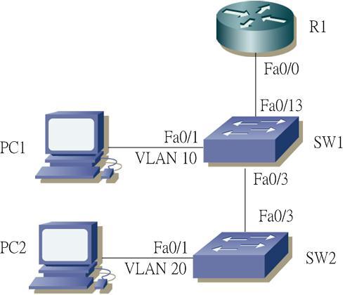
Objective of the lab is quite simple, just use the Router to do inter-vlan routing. PC1 will be put on VLAN 10, while PC2 will be put on VLAN 20.
Now in SW1, create VLAN 10, configure port 0/1 to be VLAN 10. While port 0/3 and 0/13 need to be configured as trunk and allow VLAN 10,20 traffic. Configuration as below:
hostname SW1
!
vlan 10
!
interf FastEthernet 0/1
switchport mode access
switchport access vlan 10
no shutdown
!
interf FastEthernet 0/3
switchport mode trunk
switchport trunk allowed vlan 1,10,20
no shutdown
!
interf FastEthernet 0/13
switchport mode trunk
switchport trunk allowed vlan 1,10,20
no shutdown
Similarly, in SW2, create VLAN 20, configure port 0/1 to be VLAN 20. While port 0/3 to be trunk, also allow VLAN 10,20 traffic. Configuration as below:
hostname SW2
!
vlan 20
!
interf FastEthernet 0/1
switchport access vlan 20
no shutdown
!
interf FastEthernet 0/3
switchport mode trunk
switchport trunk allowed vlan 1,10,20
no shutdown
!
Now go to the Router, create 2 subinterfaces in interface 0/0 with VLAN 10 and 20 respectively. Configure the corresponding IP addresses - VLAN 10 uses subnet 10.1.10.0/24, while VLAN 20 uses subnet 10.1.20.0/24.
interface GigabitEthernet 0/0
no shutdown
description Link to LAN Switch
ip address 10.1.1.1 255.255.255.0
!
interface GigabitEthernet 0/0.10
encapsulation dot1q 10
ip address 10.1.10.1 255.255.255.0
!
interface GigabitEthernet 0/0.20
encapsulation dot1q 20
ip address 10.1.20.1 255.255.255.0
!
Finally, for PC1 configure the corresponding IP address and default gateway as follows:
IP: 10.1.10.100 255.255.255.0
default gateway: 10.1.10.1
Similarly for PC2:
IP: 10.1.20.100 255.255.255.0
default gateway 10.1.20.1
OK, everything is ready? Should be able to ping between the PC1 and PC2.
Wait a miunte, lets first try to ping the default GW. In PC1, ping 10.1.10.1, perfectly works.
In PC2, ping 10.1.20.1. Hooops? Timeout!
So whats missing here? You may already able to figure it out. Problem is in SW1. It misses the VLAN 20. Though it doesn't has any access port on VLAN 20, it still needs to pass VLAN 20 traffic. Without the VLAN 20 definition, in fact, it won't carry VLAN 20 traffic on the trunk between it and the router. Thus VLAN 20 traffic is dropped and won't send to router.
To fix it:
sw1(config)# vlan 20
|
|
January 14, 2014 10:47:40
Posted By Kepler Lam
|
This week, I am teaching an old class Route, and just want to sum up some of my old notes about some erratic of the course material.
In the discussion of running EIGRP over NMBA (e.g. Frame Relay) network, there is a slide as below:

What's wrong with this slide (at least some pitfall)? This slide seems want to show in the case of partial mesh Frame Relay subscription, it can still work with EIGRP by configurating the IP address in main interface without using subinterface.
In fact, that’s not true. In order to make the above work, there are few things that need to cater.
- As R2 and R3 do not have a direct PVC between them, in order to make them able to communicate with each other, there must be an explicit "frame-relay map" configuration to map the remote IP to the local DLCI. Yet, wait a minute, as there is no PVC between them, so what DLCI to use? Acutally, you need to map the remote IP to the DLCI number to R1 (middle router).
- As now, R2 and R3 actually reach each other by using R1, its obvious that the interface of R1 must be up.
- Even if R2 and R3 can reach each other, it doesn’t necessary means that they can form EIGRP neighbor. In such case, you need to explicitly use the "neighbor <remote IP> <outgoing interface>" statement to manually configure EIGRP neighbor.
- But once you use the neighbor statement, the multicast method for automatic neighbor discovery will no longer work. That means, you not only need to manually configure neighbor between R2 and R3, you also need to manually configure R1 as neighbor.
- If you still want to use multicast neighbor, another method it to just let R2 and R3 forming neighbor with R1 only, without letting them to form neighbor of each other. In such case, you still need to disable split horizon for eigrp in R1 by using “no ip split-horizon eigrp <AS>” command , otherwise R2 can’t learn route from R3 (and vice versa), even thought R2 and R3 still can’t form neighbor. R2 will be able to learn route of R3 (and vice versa), next hop will become R1. You can even skip the frame-relay map (but R2 cannot directly reach R3). Following is the configuration of this method:
For R1:
hostname R1
interface Serial0/0/0
ip address 10.1.110.1 255.255.255.0
encapsulation frame-relay
no ip split-horizon eigrp 1
router eigrp 1
network 10.0.0.0
For R2:
hostname R2
interface Serial0/0/0
ip address 10.1.110.2 255.255.255.0
encapsulation frame-relay
frame-relay map ip 10.1.110.3 221
router eigrp 1
network 10.0.0.0
For R3:
hostname R3
interface Loopback1
ip address 10.1.3.1 255.255.255.0
interface Serial0/0/0
ip address 10.1.110.3 255.255.255.0
encapsulation frame-relay
frame-relay map ip 10.1.110.2 231
router eigrp 1
network 10.0.0.0
Now if you show the routing table of R2: R2#sh ip route
...
10.0.0.0/24 is subnetted, 2 subnets
D 10.1.3.0 [90/21152000] via 10.1.110.1, 00:07:34, Serial0/0/0
C 10.1.110.0 is directly connected, Serial0/0/0
What's the next hop of the route (10.1.3.0) advertised by R3?
|
|
|
|