|
November 2, 2015 09:11:15
Posted By Kepler Lam
|
In the DESIGN course, there is a question about how to bridge different network segments in different sites on to the same layer 2 network. One of the obvious solutions is using GRE tunnel between routers.
But here, I am not going to discuss how to configure GRE tunnel, as there are many documents on it. What I am going to discuss is, if you cannot change the router configuration (say if the router is not managed by you), then can you directly bridge 2 or even more Windows PC to the same layer 2 network? The solution is using the UBridge tool.
Long time ago, I have discussed how to use the Ethernet over UDP feature of UBridge. By using the new release, right now you can use the VXLAN encapsulation. Moreover, you can use the head end replication to bridge more than 2 PCs.
For example, if you have 3 different PCs on 3 sites and have IP address 10.10.1.10, 10.10.2.10 and 10.10.3.10 respectively, and want to bridge them all over subnet 10.20.1.0/24.

Then you can click here to download the UBridge tool, install the Winpcap. Create a loopback interface (or use other existing interface other than the one for the VTEP IP) in each PC. Configure the loopback interface of the 3 PCs to have IP address 10.20.1.1, 10.20.1.2 and 10.20.1.3 respectively.
Now, in PC1, execute:
C:\> ubdg 5000#V:E@10.10.1.10:10.10.2.10+10.10.3.10 5000#W:E
Select the loopback interface as prompted.
Similarly, under PC2:
C:\> ubdg 5000#V:E@10.10.2.10:10.10.1.10+10.10.3.10 5000#W:E
Similarly, under PC3:
C:\> ubdg 5000#V:E@10.10.3.10:10.10.1.10+10.10.2.10 5000#W:E
You should be able to ping among the loopback interfaces of all the PCs.
Some other design choose, such as it you don’t want to use the full mesh configuration, you can actually use the hub-and-spoke design by using the relay mode, you can further encrypt the traffic. Please refer to my other VXLAN blog entries.
|
|
October 23, 2015 05:24:08
Posted By Kepler Lam
|
In this last part of the blog entries, I will discuss the encryption feature of UBridge (open source tool under Windows platform) for VXLAN. As mentioned before, VXLAN just carry Ethernet frames over IP network without any encryption. As the original design of VXLAN is to be just used within Data Center, it is not a big deal without encryption.
But if you extend your VXLAN over a public network, encryption may become an important feature. As such a requirement, UBridge now supports encryption of the original Ethernet frame.
Currently, only pre share key (PSK) configuration using BlowFish encryption algorithm is being supported. Other stronger encryption algorithm maybe supported in future release. As the original goal is to make UBridge as an Ad Hoc tool that to be used example in testing environment, and not to be prolonged use.
Like other PSK technology, it’s susceptible for brute force attack. So use it at your own discretion.

To configure encryption, you just need to define a PSK and configure it after the remote VTEP parameter separated by an asterisk. Then when UBridge sends Ethernet frame over that leg, the frame will be encrypted. Obviously, all other VTEP(s) also need to be configured with the same key.
Just follow my previous example of the provider and access mode VTEPs in Part 3, if you want to encrypt traffic between them. Only the corresponding leg need to be configure with a key. Say if you want to use ‘secret’ as the key.
Then for the provider mode legs::
- Provider leg: 5000#V:E@192.168.150.35:0*secret:8472
Now execute ubdg:
C:> ubdg 5000#V:E@192.168.150.35:225.1.1.1:8472 5000#V:E@192.168.150.35:0*secret:8472
For the access mode VTEP,:
- Access mode VXLAN leg: 5000#V:E@10.10.1.63*:130.240.65.110*secret:8000
Now execute ubdg:
C:> ubdg 5000#V:E@10.10.1.63*:130.240.65.110*secret:8000 5000#W:E
|
|
October 23, 2015 04:32:38
Posted By Kepler Lam
|
As discussed in part 1 blog entry, all VTEPs must use the same UDP port number within the same VXLAN. This is a hindrance to extending the VXLAN to some VTEPs behind a PAT device. Unless static NAT or port mapping is being used.
Furthermore, even with the unicast mode, which can be used among VTEPs over the Internet. But it still requires the VTEP addresses to be known from each other. That further prevents VTEP device to move around behind NAT devices, as the IP address is no longer static in such case.
It’s not surprising that the VXLAN has such limitations, since most of VTEP devices are static devices that not being move around. But with the UBridge which can be executed in Windows platforms, i.e. you can run it in your laptop PC and move around anywhere.
Now with a new innovation of dynamic VTEP, you can still able to bridge your Windows laptop even behind any PAT device over the Internet, just like a remote access VPN. Dynamic VTEP consist of two different VTEP modes:
- Provider mode VTEP (like a VPN server) – which allows a VTEP device to be configured without specifying the remote VTEPs. It dynamically learns the remote VTEP address and UDP port number.
- Access mode VTEP (like a VPN client) – which allows a VTEP device without a fixed global IP and be placed behind any PAT device.
Note that the provider mode VTEP still requires a global IP and a fixed port number, despite that it can be statically mapped behind NAT device.
To configure a provider mode VTEP and relay to other VXLAN, you just need to create a leg and specific ‘0’ as the remote VTEP parameter. And create other legs for other VXLAN domain.
Example, to configure your Windows machine as a provider mode VTEP, suppose your PC has an IP address 192.168.150.35 which will be the VTEP address connected to the IP network. You need to relay remote access mode VTEP to an existing data center VXLAN that uses a standard multicast mode with multicast group address 225.1.1.1 using VNID 5000 and UDP port number 8472. (Of course, HER mode VTEPs can also be relayed).

Then create 2 legs::
- Bridge to data center VXLAN: 5000#V:E@192.168.150.35:225.1.1.1:8472
- Provider leg: 5000#V:E@192.168.150.35:0:8472
Now execute ubdg:
C:> ubdg 5000#V:E@192.168.150.35:225.1.1.1:8472 5000#V:E@192.168.150.35:0:8472
For the access mode VTEP, just put an asterisk on the local VTEP address parameter. For example, suppose your local PC is now behind a PAT router, and has an internal IP address 10.10.1.63. Suppose the above provider mode VTEP is mapped with a global IP 130.240.65.110 and UDP port 8000. You want to bridge a local loopback interface of your PC to the data center VXLAN. Then create 2 legs:
- Access mode VXLAN leg: 5000#V:E@10.10.1.63*:130.240.65.110:8000
- Winpcap leg for your loopback (UBridge will let you to select NIC to be bridged): 5000#W:E
Now execute ubdg:
C:> ubdg 5000#V:E@10.10.1.63*:130.240.65.110:8000 5000#W:E
Select the loopback interface when prompted.
|
|
October 23, 2015 04:30:38
Posted By Kepler Lam
|
As discussed before, original VXLAN standard defines that BUM frames are carried over IP multicast packets. But as many data center network is not multicast enable, so eventually different vendors have enhanced the VXLAN by using unicast mode (head end replication – HER).
UBridge supports both modes at the same time with one single VTEP address, so that you can extend a multicast mode VXLAN with other unicast VTEPs.
Before discuss the configuration of UBridge, lets take a look on the pros and cons of the these 2 modes:
- Just imagine the overlay IP network that used to carry the Ethernet frames as a very large layer 2 switch. The BUM frames are those that need to be replicated to all outgoing ports in original switch design, then it makes sense to use IP multicast packets to carry those frames to multiple destinations. The pros is that the local VTEP doesn’t need to define all the other remote VTEPs, instead all VTEPs just need to join the same multicast group.
- On the other hand, for unicast mode, all VTEPs need to know each others in order to replicate the BUM frames to other VTEPs. i.e the VTEPs are need to be fully mesh, which obviously causes scalability issues on numbers of VTEPs.
In order to solve the scalability issue, UBridge can bridge different VXLAN domain together as one single VXLAN. Here the term VXLAN domain refer to a set of VTEPs that either uses multicast mode or in a full mesh unicast configuration. UBridge can act as a relay (just like the route reflector of BGP), so that not all VTEPs need to know each others.
You can indefinitely cascade as many as VXLAN domains by UBridge to form a very large VXLAN.
Now let me discuss the configuration. If you already follow some of my previous blog entries, then you should know that the UBridge uses the concept of session legs. In order to relay several VXLAN domains, you need to configure one leg for each domain.
Example, if your local PC has an IP address 10.10.1.63 which will be the VTEP address connected to the IP network. You want to bridge the following to VXLAN with VNID 5000 using default UDP port number 4789:
- PC’c local loopback interface
- A VXLAN that uses standard multicast mode with multicast group address 225.1.1.1.
- And two other unicast mode VTEPs 10.10.1.33 and 10.80.1.1 which will be in full mesh with your local VTEP.
- One more standalone VTEP 10.2.1.30 to the VXLAN. The VNID to be used is 5000.

Then you need to create 4 legs in which 3 of them belong to VXLAN type, one belongs to Winpcap type.
For the 3 different VXLAN legs:
- Bridge to multicast VXLAN: 5000#V:E@10.10.1.63:225.1.1.1
- Bridge to 2 full mesh VTEPs: 5000#V:E@10.10.1.63:10.10.1.33+10.80.1.1
- Bridge to the standalone VTEP: 5000#V:E@10.10.1.63:10.2.1.30
For the Winpcap leg, if you know the Winpcap name of the loopback interface e.g. \Device\NPF_{5F97CBE5-7D16-48FB-BC77-0E0DE084F049}, then the leg will have the syntax:
5000#W:E@\Device\NPF_{5F97CBE5-7D16-48FB-BC77-0E0DE084F049}Or just use: 5000#W:E
Now execute ubdg:
C:> ubdg 5000#V:E@10.10.1.63:225.1.1.1 5000#V:E@10.10.1.63:10.10.1.33+10.80.1.1 5000#V:E@10.10.1.63:10.2.1.30 5000#W:E@\Device\NPF_{5F97CBE5-7D16-48FB-BC77-0E0DE084F049}
|
|
October 22, 2015 10:34:18
Posted By Kepler Lam
|
Currently, VXLAN is normally only used within the Data Center. It is rare to extend the VXLAN over the Internet. Since there are limitations on the original VXLAN specification that makes it hard to implement over the Internet.
However, by using the new released UBridge tool (inside the iptools project of sourceforge) wihich implements some unique enhanced features over the original specification, that let you easily extend the data center VXLAN anywhere, any time to any Windows PC.

The original specification has few restrictions that haven’t been addressed for extending the VXLAN over the Internet. The restrictions are:
- Original VXLAN defines that BUM frames are carried over IP multicast packet. Yet, the Internet is not multicast enable.
- Although VXLAN used UDP to carry Ethernet frame over the IP network, original specification requires that all VTEPs must use the same UDP port number within the same VXLAN. This makes it difficult to extend VTEPs that behind a PAT router/firewall to bridge with the data center VTEPs. As the UDP port number may change after the router/firewall.
- The other obvious problem is the security issue, as VXLAN doesn’t encrypt the original Ethernet frame, thus it’s not safe to extend VXLAN over Internet.
To address the above issues, UBridge has the following enhancements:
- Instead of using multicast, UBridge can use unicast to replicate BUM frames to other VTEPs. Though this is not a new concept, as other venders also have such extension. However, UBridge can use one single VTEP IP address to support both multicast and unicast mode at the same time. It means that you can use the UBridge to relay a VXLAN in data center that uses multicast mode to other VTEPs on the Internet that uses unicast mode.
- A unique feature which is called provider (like server) and access (like client) mode VTEPs has been implemented. So that devices behind PAT device can act as access mode VTEP to initiate sending traffic to VTEPs that are in provider mode (usually in data center that need to be mapped with a global IP). Once the provider mode VTEP receives traffic from access mode VTEP, it will use the UDP port number of the access VTEP for returning traffic.
- Pre-share key encryption that uses the blowfish cipher is now supported, so that it can safely carry VXLAN traffic over the Internet.
Another important factor is that UBridge can be run in almost all kinds of Windows O.S. such as XP, Win 7/8, Win Server, so you can directly bridge your standalone PC to the VXLAN without using any other VXLAN gateway device. UBridge is open source freeware and execute in user mode. You don’t even need to install it, if you don’t need to bridge local NIC (e.g. just use it as a multicast and unicast relay), you can directly execute it on USB flash. Even if for the local NIC bridging, you need just installing the Winpcap but not the UBridge itself.
The coming blog entries will discuss the above features in detail.
|
|
October 11, 2015 09:29:39
Posted By Kepler Lam
|
In recent blog entries, I have discussed how to use the UBridge tool to bridge standalone Windows PC to any VXLAN over the IP network. UBridge is a open source tool that can run on most of Intel base Windows system such as XP, Windows 7, Windows 8 and other Windows servers.
You don’t even need to install it, all you need just to install the Winpcap. By using UBridge, you don’t’ need any VXLAN gateway switch or Linux system, as UBridge is like an internal switch that can directly bridge your PC’s NIC to the VXLAN.
As UBridge is implemented according to RFC, it’s fully compatible with the standard multicast transport for BUM frame. So you can use UBridge to integrate with other vender’s VXLAN implementation, such as NSX of VMware, N1000v of Cisco, Arista switch etc.
Besides, inside the release of iptools 0.98, UBridge also supports the Head End Replication (HER) using static configuration of remote VTEPs. It was tested to be compatible with Arista HER implementation.
Just like all other tunneling technology (e.g. GRE or IPsec), as there is additional overhead on the original Ethernet frame, so you may need to adjust the MTU of the NICs. Despite that, I have tested different applications by bridging the PCs using the UBridge. Even without changes any MTU size, most of the applications such as remote desktop, FTP and even TFTP still work fine.
However, that’s not all the case. One of the examples I want to show you is the telnet to the Arista switch over VXLAN. Using the setup as in this blog entry, I can smoothly telnet to the SVI which is actually on the VXLAN of the Arista switch using the Windows interface that being bridged.
To generate a large packet, just issue some commands that will generate a long output. A simple test is just type “show ?”. Now, the telnet just display few lines, then the whole telnet session will hang.

Why is it? Most likely because of the MTU issue. As discussed before, VXLAN is a tunneling technology that uses the IP network to carry over the Ethernet frame. Below is a VXLAN packet.

Lets calculate the overhead. The original Ethernet frame is encapsulated over any frame that have another outer Ethernet header (14 bytes), IP header (20 bytes), UDP header (8 bytes) and VXLAN header (8 bytes). A total of 50 bytes.
Of course, if you can increase the MTU size of the transit IP network for 50 bytes, then that will be the best solution. Yet, that’s not always practical (e.g. due to the hardware limitation of the physical interface). Then the alternation is to decrease the MTU size of the VXLAN interface that being bridged.
So in the Arista switch, I lower the MTU size of the SVI. Lets check the original MTU size as below:

So change it to be 1450 bytes.

Now restart another telnet session, the “show ?” works perfectly.

|
|
October 1, 2015 01:22:36
Posted By Kepler Lam
|
In this example, I will demonstrate how to configure VXLAN HER (head end replication) of the UBridge to bridge with the Arista switch.
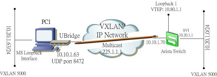
The setup is as below:
- 2 different standalone Windows machine running the UBridge with physical interface IP (VTEP) address 10.10.1.33/24 and 10.10.1.63 respectively, their loopback interface with IP address 10.20.1.33//24 and 10.20.1.63/24 respectively are to be bridged on VXLAN 5000.
- Arista switch with a routed port (interface E1) using IP address 10.10.1.70, but this address is not for the VTEP, since Arista doesn’t allow physical interface as the source interface of the VTEP. It requires using a loopback interface, so I use 10.80.1.1 on interface loopback 1 as the VTEP. This address needs to be routable among the VTEPs of the 2 Windows PC. A SVI on VLAN 100 with IP address 10.20.1.1/24 will be bridged to the VXLAN 5000.

To summarize:
- VNID is 5000
- The VTEPs: 10.10.1.33 and 10.10.1.63 (standalone PC), 10.80.1.1 (Arista)
- UDP port 8472
- VXLAN subnet 10.20.1.0/24
Configuration of the Arista switch:
Step 1. Create the loopback interface
interface Loopback1
ip address 10.80.1.1/32
Step 2. Create the VLAN 100 and SVI
vlan 100
interface Vlan100
ip address 10.20.1.1/24
Step 3. Enable routing and configure the interface E1 as a routed port
ip routing
!
interface Ethernet1
no switchport
ip address 10.10.1.70/24
Step 4. Create the VXLAN and bridge with the VLAN 100
interface Vxlan1
vxlan source-interface Loopback1
vxlan udp-port 8472
vxlan vlan 100 vni 5000
vxlan flood vtep 10.10.1.33 10.10.1.63
On Windows PC:
Before executing the UBridge, need to make the Windows VTEP routable to the loopback interface of the Arista. To make it simple, just add a static route in 2 of the Windows PC:
C:\> route add 10.80.1.0 mask 255.255.255.0 10.10.1.70
Then execute the UBridge on PC 10.10.1.33 (please refer to my previous blog entry for the explanation of this command):
C:\>ubdg 5000#V:E@10.10.1.33:10.10.1.63+10.80.1.1 5000#W:E
Similarly, for PC 10.10.1.63:
C:\>ubdg 5000#V:E@10.10.1.63:10.10.1.33+10.80.1.1 5000#W:E
Now I can ping between the Windows PCs and the VLAN interface of the Arista switch.
You find that the Arista switch learns the VTEP address of the Windows, also the MAC address of the Windows loopback interfaces in the MAC address table.

Thats not the end, you can follow my next blog entry for the discussion of the MTU size issue of VXLAN.
|
|
October 1, 2015 01:11:11
Posted By Kepler Lam
|
Here, I am going to discuss the VXLAN head end replication (HER) feature of UBridge. I have demonstrated how to use UBridge to bridge standalone Windows machines to VXLAN in previous blog entries. The previous discussions make use of standard multicast transport for BUM (broadcast, unknown unicast and multicast) frames.
However, as multicast is not commonly enabled in most IP networks, which is a hindrance of VXLAN implementation. The other solution is using head end replication – the head end VTEP replicates all BUM frames to other VTEPs by unicast IP packets.
Currently, there is no standard of the HER implementation. Cisco Nexus 1000v implement a proprietary method which making use of a control signal that the VEMs register their VTEPs to the VSM, so that the VSM can notify all the VEMs about the VTEPs address.
While Arista uses a simpler method that just manually defines all the remote VTEPs address in each end point, so that there is no control signal to be defined.
Just like Arista, the open source UBridge tool (which is inside the Iptools package under sourceforge.net) also supports the HER by manual configuration of remote VTEPs. UBridge acts as a virtual switch in MS Windows environment, similar to the OpenSwitch in Linux. UBridge can bridge physical or logical interfaces (e.g. loopback or VMnet) of Windows to the VXLAN or using Ethernet over UDP. UBridge also support Ethernet over UDP.

To bridge a Windows’ interface to VXLAN on remote VTEP, you need to create 2 legs – one is for the Windows interface to be bridged, the other is to the VXLAN.
You can refer to my other blog for the multicast configuration. Actually the difference is only the VXLAN leg for the HER configuration.
The syntax is:
<VNID>#V:E@<local_vtep>:<remote_vtep>[+<remote_vtep>]...[:<port>]
E.g. to bridge your local loopback interface using your local VTEP address 10.10.1.33 to 2 other VTEPs with IP address 10.10.1.63 and 10.80.1.1 using UDP port 8472.
Then execute the following command:
C:\>ubdg 5000#V:E@10.10.1.33:10.10.1.63+10.80.1.1:8472 5000#W:E
UBridge will prompt you to select the interface to be bridged (e.g. loopback), note that DO NOT select the interface with the VTEP address.
Please follow the next blog entry for the example of HER using the UBridge and the Arista switch.
|
|
September 23, 2015 07:35:00
Posted By Kepler Lam
|
In previous blog entries, I have discussed how to use UBridge to bridge local Windows machines to VXLAN with Cisco Nexus 1000v. Now, I want to add the integration with the Arista switch.
Using the same environment as before:
- Standalone Windows machine running the UBridge with physical interface IP address 10.10.1.63 as the VTEP, the loopback interface with IP address 10.20.1.63/24 to be on VXLAN 5000
- Arista switch (I use the virtual edition 4.14.5F and installed in VMWare workstation) with a routed port (interface E1) using IP address 10.10.1.70, but this address is not for the VTEP, since Arista doesn’t allow physical interface as the source interface of the VTEP. It requires using a loopback interface, so I use 10.80.1.1 on interface loopback 1 as the VTEP. This address need to be routable among all the other VTEPs. A SVI on VLAN 100 with IP address 10.20.1.1/24 will be bridged to the VXLAN.
To summarize:
- VNID is 5000
- The VTEPs: 10.10.1.63 (standalone PC), 10.10.1.68 (ESX), 10.80.1.1 (Arista)
- Multicast group 225.1.1.1 and UDP port 8472
- VXLAN subnet 10.20.1.0/24
Configuration of the Arista switch:
Step 1. Create the loopback interface
interface Loopback1
ip address 10.80.1.1/32
Step 2. Create the VLAN 100 and SVI
vlan 100
interface Vlan100
ip address 10.20.1.1/24
Step 3. Configure the interface E1 and enable both unicast and multicast routing
ip routing
!
ip multicast-routing
!
interface Ethernet1
no switchport
ip address 10.10.1.70/24
ip pim sparse-mode
Step 4. Create the VXLAN and bridge with the VLAN 100
interface Vxlan1
vxlan multicast-group 225.1.1.1
vxlan source-interface Loopback1
vxlan udp-port 8472
vxlan vlan 100 vni 5000
On Windows PC:
Before executing the Ubridge, need to make the Windows VTEP routable to the loopback interface of the Arista. To make it simple, just add a static route in the Windows:
C:\> route add 10.80.1.0 mask 255.255.255.0 10.10.1.70
Then execute the Ubridge:
C:\>ubdg 5000#V:E@10.10.1.63:225.1.1.1 5000#W:E
Now I can ping between the Windows and the VLAN interface of the Arista switch.

To verify in the Arista switch:

You find that the Arista switch learns the VTEP address of the Windows, also the MAC address of the Windows loopback interface in the MAC address table.
|
|
August 24, 2015 07:53:48
Posted By Kepler Lam
|
This blog entry explains the detail about the UBridge Tool configuration for bridging to the VXLAN.
As VXLAN is only available in the VM environment, it only allows the VMs inside ESX servers (either the same or different ESX) within the same VXLAN to be able to communicate. Yet, for all other standalone hosts that are not inside ESXi servers cannot directly commuicated with VMs on VXLAN unless using a VXLAN gateway to bridge the VXLAN to traditional VLAN.
Now by using the Ubridge tool which is freely available inside the IPtools package, you can bridge any interfaces within your Windows PC over the IP network to the VXLAN inside ESX servers.
For example if you have a VMware infrastructure that has a VXLAN with VNID 5000 using multicast group 225.1.1.1.
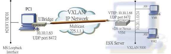
To bridge your local Windows PC to this VXLAN, your PC will require:
- Physical NIC card connected to the IP network that can reach the VTEPs of the other ESX servers using multicast.
- Another network interface which can be physical or virtual interface (e.g. you can create a MS loopback interface) that would be used to bridge with the VXLAN.
The concept is to create two legs under the group 5000: one leg is your physical NIC that joins the IP network, the other leg is for the interface to be bridged to the VXLAN.
For the physical NIC, find out your local IP address (e.g. 10.10.1.63) that will be the VTEP address. The leg type is VXLAN (V), Ethernet subtype (E), the VNID 5000 and multicast group 225.1.1.1. Syntax of this leg:
5000#V:E@10.10.1.63:225.1.1.1
For the 2nd leg, if you know the Winpcap name of the interface to be bridge, you can specify it as the parameter (most tools such as Wireshark or GNS3 provide a way to find it out). But don't worry, even if you don't have this information, just omit the corresponding parameter, UBrdige will prompt you to choose. This leg type is Winpcap (W), Ethernet subtype (E), E.g. if the name of the loopback interface is \Device\NPF_{5F97CBE5-7D16-48FB-BC77-0E0DE084F049}, then the leg will have the syntax:
5000#W:E@\Device\NPF_{5F97CBE5-7D16-48FB-BC77-0E0DE084F049}
or just use
5000#W:E
Now invoke the UBridge with the above 2 legs:
C:> ubdg 5000#V:E@10.10.1.63:225.1.1.1 5000#W:E@\Device\NPF_{5F97CBE5-7D16-48FB-BC77-0E0DE084F049}
or simply:
C:> ubdg 5000#V:E@10.10.1.63:225.1.1.1 5000#W:E
Now you should able to ping between the loopback interface of the your PC and the VM on the VXLAN inside the ESX server.
- Kepler
Certified Cisco instructor since 1998
|
|
|
|