|
October 1, 2015 01:22:36
Posted By Kepler Lam
|
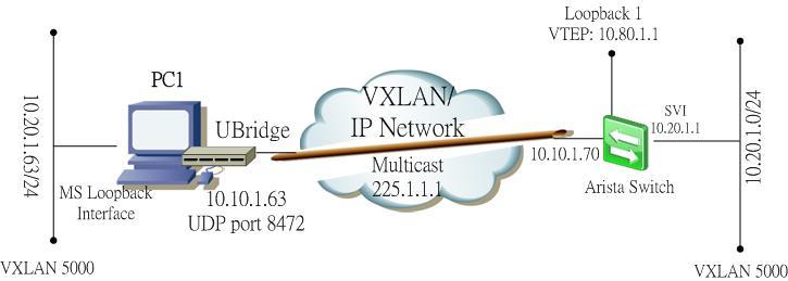
In this example, I will demonstrate how to configure VXLAN HER (head end replication) of the UBridge to bridge with the Arista switch.
The setup is as below:
- 2 different standalone Windows machine running the UBridge with physical interface IP (VTEP) address 10.10.1.33/24 and 10.10.1.63 respectively, their loopback interface with IP address 10.20.1.33//24 and 10.20.1.63/24 respectively are to be bridged on VXLAN 5000.
- Arista switch with a routed port (interface E1) using IP address 10.10.1.70, but this address is not for the VTEP, since Arista doesn’t allow physical interface as the source interface of the VTEP. It requires using a loopback interface, so I use 10.80.1.1 on interface loopback 1 as the VTEP. This address needs to be routable among the VTEPs of the 2 Windows PC. A SVI on VLAN 100 with IP address 10.20.1.1/24 will be bridged to the VXLAN 5000.

To summarize:
- VNID is 5000
- The VTEPs: 10.10.1.33 and 10.10.1.63 (standalone PC), 10.80.1.1 (Arista)
- UDP port 8472
- VXLAN subnet 10.20.1.0/24
Configuration of the Arista switch:
Step 1. Create the loopback interface
interface Loopback1
ip address 10.80.1.1/32
Step 2. Create the VLAN 100 and SVI
vlan 100
interface Vlan100
ip address 10.20.1.1/24
Step 3. Enable routing and configure the interface E1 as a routed port
ip routing
!
interface Ethernet1
no switchport
ip address 10.10.1.70/24
Step 4. Create the VXLAN and bridge with the VLAN 100
interface Vxlan1
vxlan source-interface Loopback1
vxlan udp-port 8472
vxlan vlan 100 vni 5000
vxlan flood vtep 10.10.1.33 10.10.1.63
On Windows PC:
Before executing the UBridge, need to make the Windows VTEP routable to the loopback interface of the Arista. To make it simple, just add a static route in 2 of the Windows PC:
C:\> route add 10.80.1.0 mask 255.255.255.0 10.10.1.70
Then execute the UBridge on PC 10.10.1.33 (please refer to my previous blog entry for the explanation of this command):
C:\>ubdg 5000#V:E@10.10.1.33:10.10.1.63+10.80.1.1 5000#W:E
Similarly, for PC 10.10.1.63:
C:\>ubdg 5000#V:E@10.10.1.63:10.10.1.33+10.80.1.1 5000#W:E
Now I can ping between the Windows PCs and the VLAN interface of the Arista switch.
You find that the Arista switch learns the VTEP address of the Windows, also the MAC address of the Windows loopback interfaces in the MAC address table.

Thats not the end, you can follow my next blog entry for the discussion of the MTU size issue of VXLAN.
|
|
October 1, 2015 01:11:11
Posted By Kepler Lam
|
Here, I am going to discuss the VXLAN head end replication (HER) feature of UBridge. I have demonstrated how to use UBridge to bridge standalone Windows machines to VXLAN in previous blog entries. The previous discussions make use of standard multicast transport for BUM (broadcast, unknown unicast and multicast) frames.
However, as multicast is not commonly enabled in most IP networks, which is a hindrance of VXLAN implementation. The other solution is using head end replication – the head end VTEP replicates all BUM frames to other VTEPs by unicast IP packets.
Currently, there is no standard of the HER implementation. Cisco Nexus 1000v implement a proprietary method which making use of a control signal that the VEMs register their VTEPs to the VSM, so that the VSM can notify all the VEMs about the VTEPs address.
While Arista uses a simpler method that just manually defines all the remote VTEPs address in each end point, so that there is no control signal to be defined.
Just like Arista, the open source UBridge tool (which is inside the Iptools package under sourceforge.net) also supports the HER by manual configuration of remote VTEPs. UBridge acts as a virtual switch in MS Windows environment, similar to the OpenSwitch in Linux. UBridge can bridge physical or logical interfaces (e.g. loopback or VMnet) of Windows to the VXLAN or using Ethernet over UDP. UBridge also support Ethernet over UDP.

To bridge a Windows’ interface to VXLAN on remote VTEP, you need to create 2 legs – one is for the Windows interface to be bridged, the other is to the VXLAN.
You can refer to my other blog for the multicast configuration. Actually the difference is only the VXLAN leg for the HER configuration.
The syntax is:
<VNID>#V:E@<local_vtep>:<remote_vtep>[+<remote_vtep>]...[:<port>]
E.g. to bridge your local loopback interface using your local VTEP address 10.10.1.33 to 2 other VTEPs with IP address 10.10.1.63 and 10.80.1.1 using UDP port 8472.
Then execute the following command:
C:\>ubdg 5000#V:E@10.10.1.33:10.10.1.63+10.80.1.1:8472 5000#W:E
UBridge will prompt you to select the interface to be bridged (e.g. loopback), note that DO NOT select the interface with the VTEP address.
Please follow the next blog entry for the example of HER using the UBridge and the Arista switch.
|
|
September 23, 2015 07:35:00
Posted By Kepler Lam
|
In previous blog entries, I have discussed how to use UBridge to bridge local Windows machines to VXLAN with Cisco Nexus 1000v. Now, I want to add the integration with the Arista switch.
Using the same environment as before:
- Standalone Windows machine running the UBridge with physical interface IP address 10.10.1.63 as the VTEP, the loopback interface with IP address 10.20.1.63/24 to be on VXLAN 5000
- Arista switch (I use the virtual edition 4.14.5F and installed in VMWare workstation) with a routed port (interface E1) using IP address 10.10.1.70, but this address is not for the VTEP, since Arista doesn’t allow physical interface as the source interface of the VTEP. It requires using a loopback interface, so I use 10.80.1.1 on interface loopback 1 as the VTEP. This address need to be routable among all the other VTEPs. A SVI on VLAN 100 with IP address 10.20.1.1/24 will be bridged to the VXLAN.
To summarize:
- VNID is 5000
- The VTEPs: 10.10.1.63 (standalone PC), 10.10.1.68 (ESX), 10.80.1.1 (Arista)
- Multicast group 225.1.1.1 and UDP port 8472
- VXLAN subnet 10.20.1.0/24
Configuration of the Arista switch:
Step 1. Create the loopback interface
interface Loopback1
ip address 10.80.1.1/32
Step 2. Create the VLAN 100 and SVI
vlan 100
interface Vlan100
ip address 10.20.1.1/24
Step 3. Configure the interface E1 and enable both unicast and multicast routing
ip routing
!
ip multicast-routing
!
interface Ethernet1
no switchport
ip address 10.10.1.70/24
ip pim sparse-mode
Step 4. Create the VXLAN and bridge with the VLAN 100
interface Vxlan1
vxlan multicast-group 225.1.1.1
vxlan source-interface Loopback1
vxlan udp-port 8472
vxlan vlan 100 vni 5000
On Windows PC:
Before executing the Ubridge, need to make the Windows VTEP routable to the loopback interface of the Arista. To make it simple, just add a static route in the Windows:
C:\> route add 10.80.1.0 mask 255.255.255.0 10.10.1.70
Then execute the Ubridge:
C:\>ubdg 5000#V:E@10.10.1.63:225.1.1.1 5000#W:E
Now I can ping between the Windows and the VLAN interface of the Arista switch.

To verify in the Arista switch:

You find that the Arista switch learns the VTEP address of the Windows, also the MAC address of the Windows loopback interface in the MAC address table.
|
|
August 24, 2015 07:53:48
Posted By Kepler Lam
|
This blog entry explains the detail about the UBridge Tool configuration for bridging to the VXLAN.
As VXLAN is only available in the VM environment, it only allows the VMs inside ESX servers (either the same or different ESX) within the same VXLAN to be able to communicate. Yet, for all other standalone hosts that are not inside ESXi servers cannot directly commuicated with VMs on VXLAN unless using a VXLAN gateway to bridge the VXLAN to traditional VLAN.
Now by using the Ubridge tool which is freely available inside the IPtools package, you can bridge any interfaces within your Windows PC over the IP network to the VXLAN inside ESX servers.
For example if you have a VMware infrastructure that has a VXLAN with VNID 5000 using multicast group 225.1.1.1.
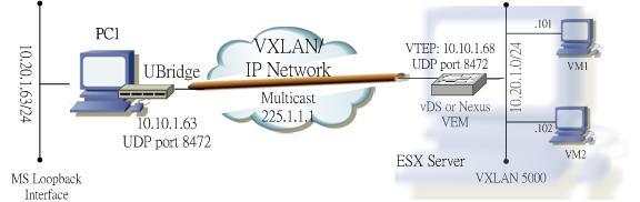
To bridge your local Windows PC to this VXLAN, your PC will require:
- Physical NIC card connected to the IP network that can reach the VTEPs of the other ESX servers using multicast.
- Another network interface which can be physical or virtual interface (e.g. you can create a MS loopback interface) that would be used to bridge with the VXLAN.
The concept is to create two legs under the group 5000: one leg is your physical NIC that joins the IP network, the other leg is for the interface to be bridged to the VXLAN.
For the physical NIC, find out your local IP address (e.g. 10.10.1.63) that will be the VTEP address. The leg type is VXLAN (V), Ethernet subtype (E), the VNID 5000 and multicast group 225.1.1.1. Syntax of this leg:
5000#V:E@10.10.1.63:225.1.1.1
For the 2nd leg, if you know the Winpcap name of the interface to be bridge, you can specify it as the parameter (most tools such as Wireshark or GNS3 provide a way to find it out). But don't worry, even if you don't have this information, just omit the corresponding parameter, UBrdige will prompt you to choose. This leg type is Winpcap (W), Ethernet subtype (E), E.g. if the name of the loopback interface is \Device\NPF_{5F97CBE5-7D16-48FB-BC77-0E0DE084F049}, then the leg will have the syntax:
5000#W:E@\Device\NPF_{5F97CBE5-7D16-48FB-BC77-0E0DE084F049}
or just use
5000#W:E
Now invoke the UBridge with the above 2 legs:
C:> ubdg 5000#V:E@10.10.1.63:225.1.1.1 5000#W:E@\Device\NPF_{5F97CBE5-7D16-48FB-BC77-0E0DE084F049}
or simply:
C:> ubdg 5000#V:E@10.10.1.63:225.1.1.1 5000#W:E
Now you should able to ping between the loopback interface of the your PC and the VM on the VXLAN inside the ESX server.
- Kepler
Certified Cisco instructor since 1998
|
|
August 24, 2015 07:13:09
Posted By Kepler Lam
|
To setup the VXLAN in the Nexus 1000v, just follow this Cisco guide.
Configuration steps as follows:
Step 1. Enable the VXLAN Feature
feature segmentation
Note that don’t be confused with the Cisco’s example. Though it just mentions to turn on the segmentation feature, the show feature output also display the network-segmentation feature. So I also turn the later on, that is a MISTAKE! As I find out that if the network-segmentation feature is on, the VEM will never send out multicast packets. It waste me almost a day to figure out the problem.
Step 2. Configure the Default Mode
no segment mode unicast-only
Step 3. Configure the VTEP Port-Profile
For the VTEP VLAN, as I will configure the VTEP address (10.10.1.68) inside the subnet of my local PC, and recall that my ESX’s NIC actually bridge to my local PC, thus I use VLAN 1 (which is the native VLAN).
The VNID (VXLAN ID) to be used is 5000 with multicast group 225.1.1.1 (default Cisco UDP port 8472).
port-profile type vethernet VTEP
vmware port-group
switchport mode access
switchport access vlan 1
capability vxlan
no shutdown
state enabled
Step 4. Create the VTEP VMKernel Interfaces (under vCenter)
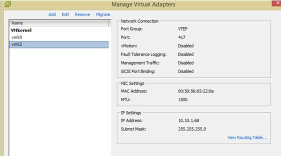
Note that in my environment, it requires to "shut" and "no shut" the corresponding VTEP interface in the VSM to make it works.
Step 5. Create the Bridge Domain
bridge-domain 10.20.1..x
segment id 5000
group 225.1.1.1
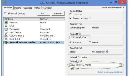
Step 6. Create the VXLAN Port-Profile for VMs
Port-profile type vethernet vxlan-10.20.1.x
vmware port-group
switchport mode access
switchport access bridge-domain 10.20.1.x
no shutdown
state enabled
Step 7. Assign the VXLAN Port-Profile to VMs (under vCenter)
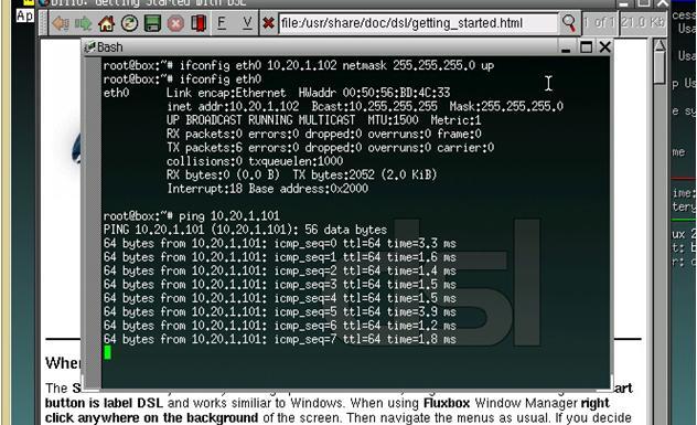
The NICs of the 2 different DSL VMs (with IP address 10.20.1.101 and 10.20.1.102 respectively) are changed to use the VXLAN portgroup.
Now I can ping between the 2 different VMs.
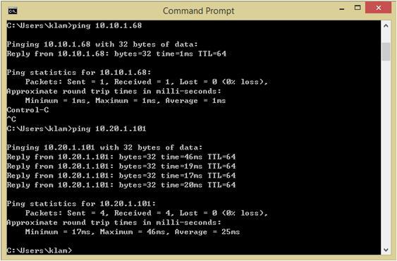
Now to bridge my loopback interface (with IP address 10.20.1.63) of my local PC to the VXLAN, I need to execute the Ubridge tool. (The next blog entry explains more detail about the UBridge configuration). My PC’s local NIC card uses IP address 10.10.1.63 which will be the VTEP address, execute the Ubridge as follow:
c:\> ubdg.bat 5000#W:E 5000#V:E@10.10.1.63:225.1.1.1
Now I can ping between my loopback interface and the 2 VM’s IP address.
|
|
August 24, 2015 06:08:22
Posted By Kepler Lam
|
In this blog entry, I want to discuss how to use the open source tool UBridge to directly bridge the Windows PC to the VXLAN without using any VXLAN gateway.
UBridge is like the vSwitch inside the ESX, but UBridge is open source and can directly execute under the Windows command prompt. It’s now available inside the IPtools package, click here to download.You don’t need to even install it, all you need is to install the Winpcap.
To setup the VXLAN testing environment, you need to have at least one ESX server, vCenter server (while I use the Linux version) and vCenter client software.
I use the Cisco Nexus 1000v to configure the vDS for the VXLAN. Yes, I use Nexus instead of NSX. Honestly, I’m not a VMware guy, I am more familiar with the Cisco technology, also I’ve already have the N1K environment for testing.
The followings are software versions that being used:
- ESXi: 5.5.0 (VMkernel release build 1623387)
- vCenter: Server Appliance 5.5.0.10000-1624811
- VSM:nexus-1000v.4.2.1.SV2.2.2.bin
- VEM: Cisco_bootbank_cisco-vem-v160-esx_4.2.1.2.2.2.0-3.2.1.vib
For the minimal hardware requirement, I used VMware workstation in my local PC, and install the ESX as a guest VM, bridge the ESX NIC as my local PC’s NIC. Likewise, the vCenter server is also a guest VM of the VMware workstation.
I created 2 smallest VMs inside the ESX by using the DSL linux image.
Then setup the Nexus 1000v into the VMware infrastructure, which is a long journey and not the focus of this blog, please refer to the corresponding documentation (or can hire me!).
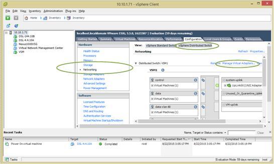
Following figures shows the ESX configuration:
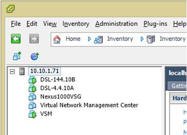
You don't actutally needs the VSG which is for my other testing.
Now, to setup the VXLAN in the Nexus 1000v, please following this next blog entry.
|
|
June 29, 2015 10:36:30
Posted By Kepler Lam
|
Just want to use the following as a troubleshooting example for service profile association. Here is a very common problem in the service profile configuration lab in the DCUCI course. (Most likely because the lab instruction is not very clear).
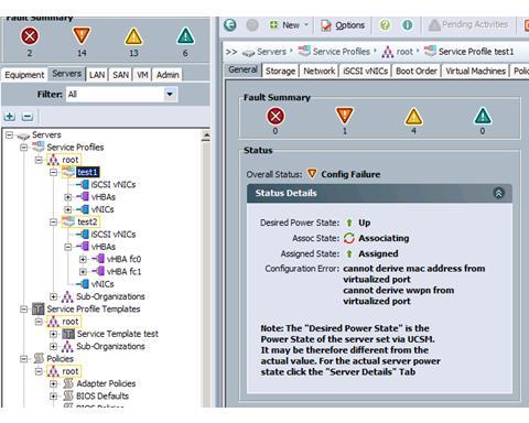
The profile fail to associate with a blade server. In the general tab of the service profile, it shows the configuration error as the following screen:
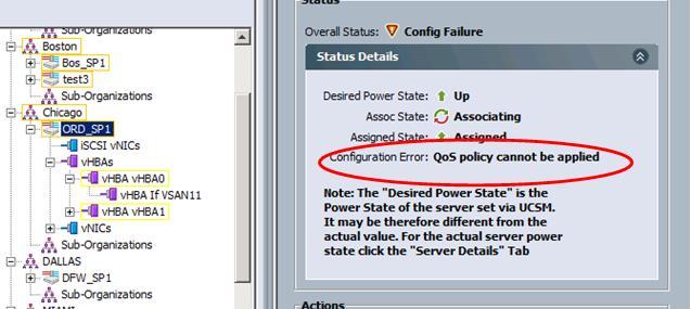
To troubleshoot, first of course need to pay attention to the error message, in this example is the QoS policy which cannot be applied. To double check, click the Faults tab to review the recent logs.
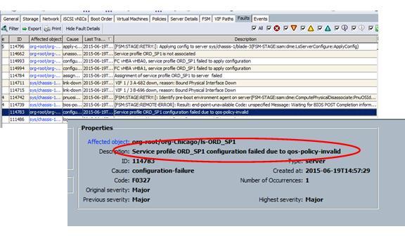
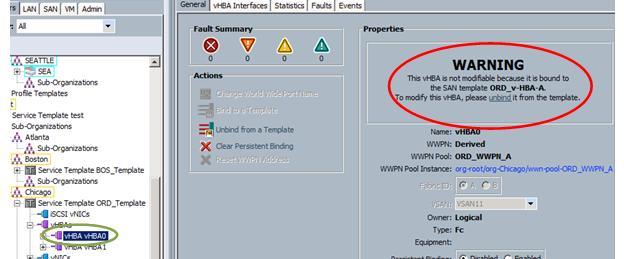
Now you confirm that it is the QoS policy problem. Then what’s next, where is the QoS being applied? One of the places being focus should be the virtual NIC, so go to the vNIC of the profile (using the Navigation pane). On the General page, though there is a warning, the QoS policy is actually applied. (Same as the 2nd vNIC).
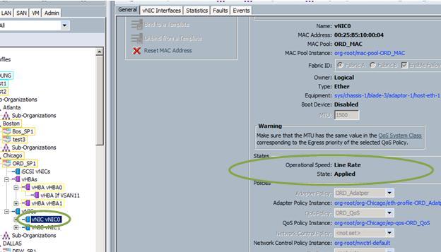
Then what other place will have the QoS policy? Right, it is the vHBA.
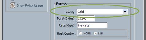
So navigate to the vHBA, and finding that the state is “line rate is failed to apply”.
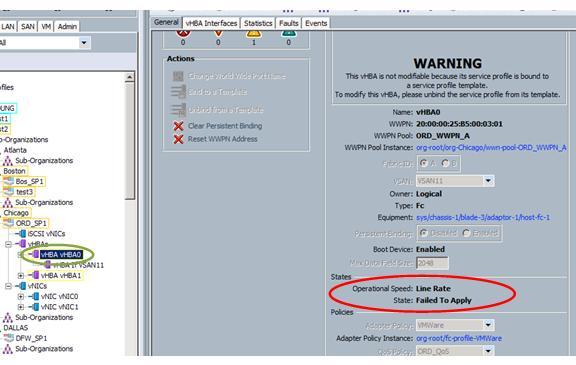
Click on the Faults tab to double check that the vHBA failed to apply configuration.
Actually the QoS policy being applied is for the vNIC, the traffic class is not marked as FC which can not be applied to the vHBA.
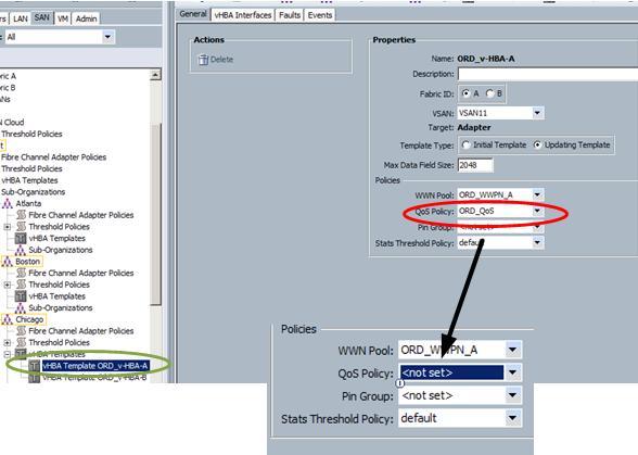
In fact, in this lab, we don’t even need to apply the QoS policy. So the simple solution is to just take out the QoS policy. Yet, from the Warning message, we know that the service profile is associated with the template. Thus we need to change the template instead of the service profile directly. Now, navigate to the vHBA of the corresponding template. Again we find that the vHBA is associated with a SAN template.
Thus, finally we need to go to the SAN template, unselect the QoS policy.
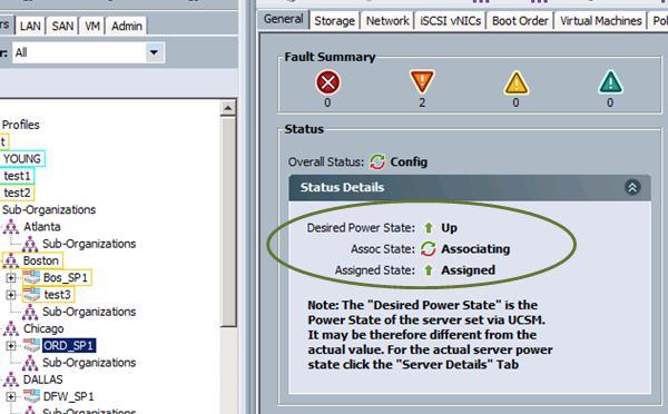
Back to the service policy, see! Its now starting to associate,
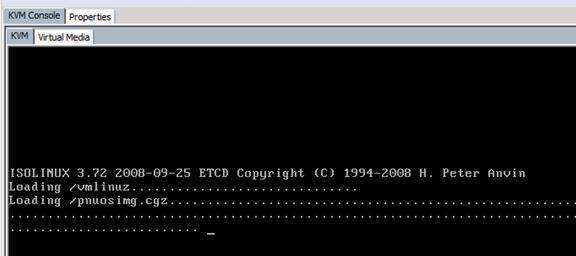
Can monitor the console by using the KVM.
|
|
June 21, 2015 09:50:05
Posted By Kepler Lam
|
In last week when I delivered the DCUCI class, one of the questions from student is: can a blade server be used immediately after plug into the chassis – strictly speaking it means can a service profile automatically be assigned to a newly plug in physical server.
The answer is yes. Actually we can pre-provision service profile i.e. a server profile assigned to an empty pool (or a pool that without any more unassigned server). Then using the pool autopopulating configuration (Create a server pool qualification by specific e.g. CPU, memory requirements. Then create a server pool policy by placing the server pool qualification and the target pool), once the new server is plugged in (and if it satisfy the pool qualification requirements), it will be automatically populated to the pool and the service profile will be immediately assigned to this new server.
Following figures illustrate the procedure.
1. Create a service profile and assigned to an empty pool. Here shows the service profile and the pool: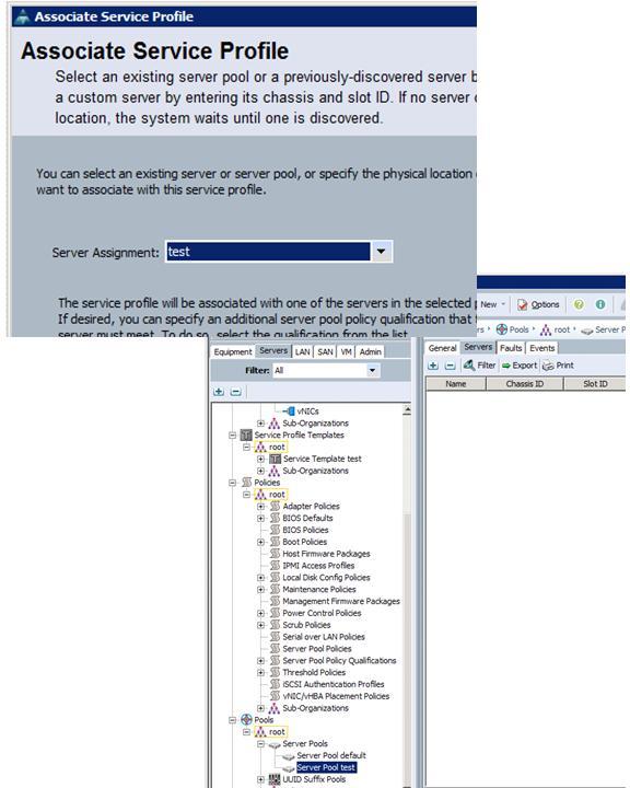
Note that the profile is in unassociated state and server assignment is failed (that’s normal at this stage).

2. Now I manually move a server to the pool (you can also use autopopulation for physically add a new server)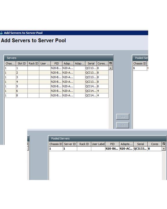
3. Then back to the service profile, now you can see that the service profile immediately assigned to the new server without any human intervention.
|
|
March 2, 2015 10:48:59
Posted By Kepler Lam
|
Just delivery the Cisco IUWNE (Implementing Cisco Unified Wireless Networking Essentials) class last week, as there is a lesson on antenna, and it has an equation showing that:
0 dbd = 2.14 dbi
As dbd is the effect compare with dipole where dbi compare with isotopic, the first glance is that dbd should be more focus, i.e. should have a greater gain, but why is lower than dbi?
Although there are webpages explain dbi and dbd, this blog entry attempt to use a more visual way to explain it (not a rigorous physic theory).
Now just think about when you apply certain electricity energy (in terms of mW) on the antenna, which actually “convert” to electromagnetic wave and “spread” out to the space.
If we use “particles” as the energy carrier, it will be easier to visual it. Just imagine that when we use an isotopic antenna, it emits particles (with equal energy and velocity) out evenly all over the space in 360 degree in all directions.
Then over the space, if we measure in a unit volume, how many particles are passing it every unit of time, actually we are measuring the rate of energy applied on it. i.e. the Power (in either mW or dbm). Obviously the closer to the antenna, the “density” of the energy particles is higher, i.e. the stronger the signal. While when you away from the antenna, the particle density drops and thus the signal strength also drops.
The effect of antenna is just alters the “path” of the particles, it will not increase the speed nor number of particles emitted (which depends on transmission power). So that some paths will be converted to a certain direction. And thus the density of particles in certain direction will be dense than using the isotopic antenna.
The gain of the antenna thus is a measurement of how “dense” it alters the movement of particles in certain unit volume of the space. Say e.g. in a certain position, when using the isotopic antenna, there are 10 particles passing thru’ it each ms. Now by using another antenna, it increases to 20 particles each ms. Then you have a gain on that particular point.
And as the dipole already has a higher gain than isotopic antenna, so if for a new antenna, when compare the effect with isotopic antenna (dbi) vs the effect of dipole (dbd), then the former should have a greater value.
|
|
December 16, 2014 03:17:58
Posted By Kepler Lam
|
Just finish the teaching of a UCCX class, one of the topics that the participants are interested is the creation of additional language. In fact, its not so difficult, here is the high level steps:
- Globally define an additional language and select the default language of a language group
- Create the corresponding language folder for different resources (e.g. prompt)
- In your script, add steps for user to select language
Let’s discuss them one by one.
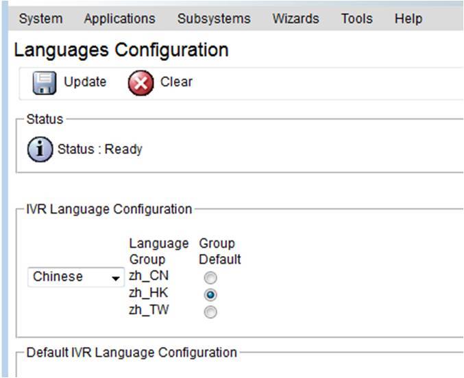
Step 1.
Login to the UCCX administration web portal, under System>Language information, select a new language that you want to configure (e.g. Chinese), then select the corresponding default for that group (e.g. Hong Kong Chinese).
Step 2.
Now navigate to the corresponding resources that you will use in the script, e.g. your script has a welcome prompt, then go to the Application>Prompt Management. Click Create Language, then under the popup window, select the new language (e.g. Chinese (HK) which will have a mnemonic as zh_HK) that you need to create.
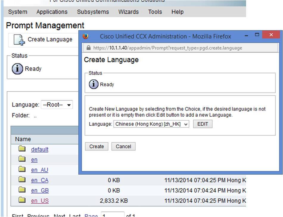
A new folder with the name of the mnemonic will be created. Browse into that folder, and in the corresponding location (that your script refer, using same hierarchy as other language), upload your new prompt in the new language.
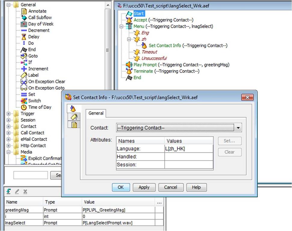
Step 3.
Then under your script, you should normally let the user select the language at the beginning of the session. So record a prompt for language selection e.g. “1 for English and 2 for Chinese”. Place this prompt file under the default language (say English) folder.
In your script, after accept the session, place a menu step using the language selection prompt. Create different language branch in this menu step, according to the selections spoken in the prompt. E.g. Eng branch when user press 1, zh branch when user select 2.
For the default language branch say Eng, you may not need to do anything. Yet for the other language branch, put a Set Contact Info step. Open the property of this step, under the general tab, put the corresponding value of the language for the language attribute.
Then that’s all. Subsequent flow of your script is the same as before, all your prompt reference is the same as your default language. As once the session change to other language, it will just get the prompt on the correct location of the corresponding language folder.
|
|
|
|