|
October 27, 2014 10:20:54
Posted By Kepler Lam
|
In previous blog entries, I have discussed how to configure the Jabber client without using the IM. In this blog, I want to discuss the opposite way i.e. configure IM only Jabber client (even without the LDAP).
Basically, it’s quite straight forward, just follow the 3 steps below:
- Configure end user in CUCM
- Start the Jabber to connect to the IM server
- Add local contact
Step 1. Configure end user in CUCM
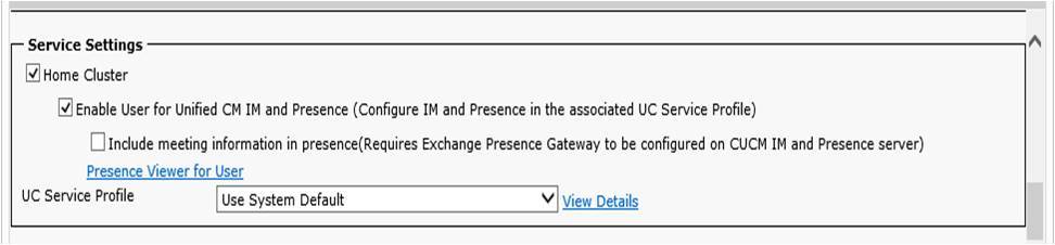
Under CUCM, navigate to User Management > End User. Add or edit enend user, Check the Enable User for Unified CM IM and Presence field, and also add the user to Standard CCM End Users if not yet added.
Step 2. Start the Jabber to connect to the IM server
Now run your Jabber as shown below (you maybe asked to reset the Jabber, also if you are not using DNS, you need to add the CUCM in the local host file of your PC, please refer to this blog):

Step 3. Add local contact (if not using LDAP)
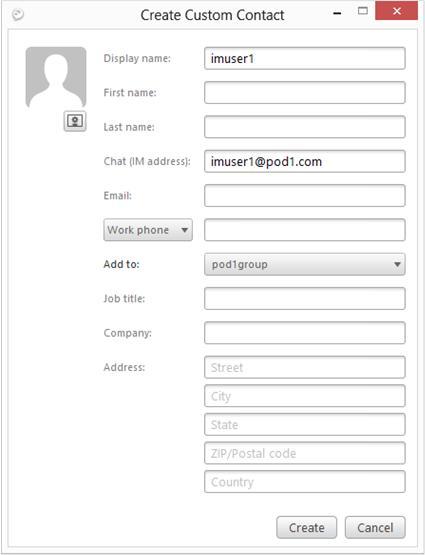
Now after login your Jabber, under the Setting > File > New > Custom contact to add a new local contact. The most important is the Chat (IM address), the username part is the other End User ID configured under CUCM, while the domain is the domain configured under the IM&P server:
You can add it to any group.
Then you should be able to chat with the other user.
|
|
September 23, 2014 05:02:58
Posted By Kepler Lam
|
Recently, just prepared a customized course about CUCM 10. One of the topics is about the Jabber on CUCM 10. It seems that it is not so clear about the Jabber integration with CUCM without the IM&P server (previous CUPS). As many of the Cisco documentation just mention how to configure Jabber to register to the IM&P server, without mentioning how to configure Jabber as a standalone (or desktop phone control) phone that doesn’t really need the IM&P. This blog entry wants to explain how to configure it.
Moreover, most of the configuration examples also involve the LDAP, DNS (though in real environment, most likely you will have those infrastructure components). Yet, you don’t need all those for the very basic configuration. All you need is:
- CUCM server (v10)
- Jabber client (v9 or 10) installed in your PC
Then you can immediately configure your Jabber as a softphone in just few steps. Here it is:
- Create a CSF device
- Add/Modify an End user
- Configure the Jabber in your PC
Step 1. Create a CSF device
Under Device > Phone, add a new phone with type Cisco Unified Client Services Framework. Specify a name for the CSF device in the Device Name. Configure all other necessary fields. Click Save.

Then configure a new directory number for the CSF device.

Step 2. Add/Modify an End user
Under User Management > End User, add or modify an end user. 
Associate the CSF phone you just created to the End user (or set the CSF device owner as the end user under step 1 above). 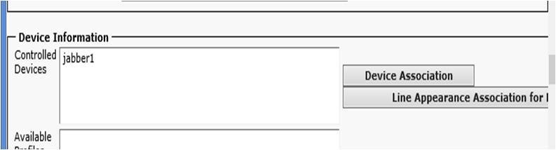
Then add the user to Standard CCM End User Group (this step is quite important, without that the Jabber will not able to login).

Please follow the other Blog entry Jabber setup without IM & Presence server (Part 2)
|
|
September 23, 2014 05:02:58
Posted By Kepler Lam
|
(Note: this blog entry follow the Jabber setup without IM & Presence server (Part 1))
Step 3. Configure the Jabber in your PC
Before that if you don’t have a DNS entry for your CUCM, you need to modify the Windows local host name table. Use any editor (e.g. notepad), edit the file \Windows\System32\drivers\etc\hosts, append the following lines to it:
<ip address of your CUCM> <hostname of your CUCM>
Again this step is very important, without it the Jabber will complain that unable to connect to the server.
Now, start your Jabber. The first time startup requires you to enter an Email address format user ID. Enter any dummy Email address format as user ID. Until it fails to connect, then you can choose the Advanced setting. Under the advanced settings, you can select the CUCM as your account type, also enter your CUCM server IP. Following is screen of Jabber 10-5. (Also tested with v9-7-4).

After save, login with the configured user. credential
Simply enough?
- Kepler
Certified Cisco Instructor
Certified Juniper Instructor
Certified H3C Instructor
Certified F5 Instructor
Unqaulified student of Jesus Christ
|
|
June 10, 2014 04:36:41
Posted By Kepler Lam
|
When teaching the F5 admin class last week, there is a lab to use cookie persistence. In order to configure this feature, you need to apply a cookie persistence profile. Yet, most students didn’t realize that there is profile dependence in the F5 configuration.
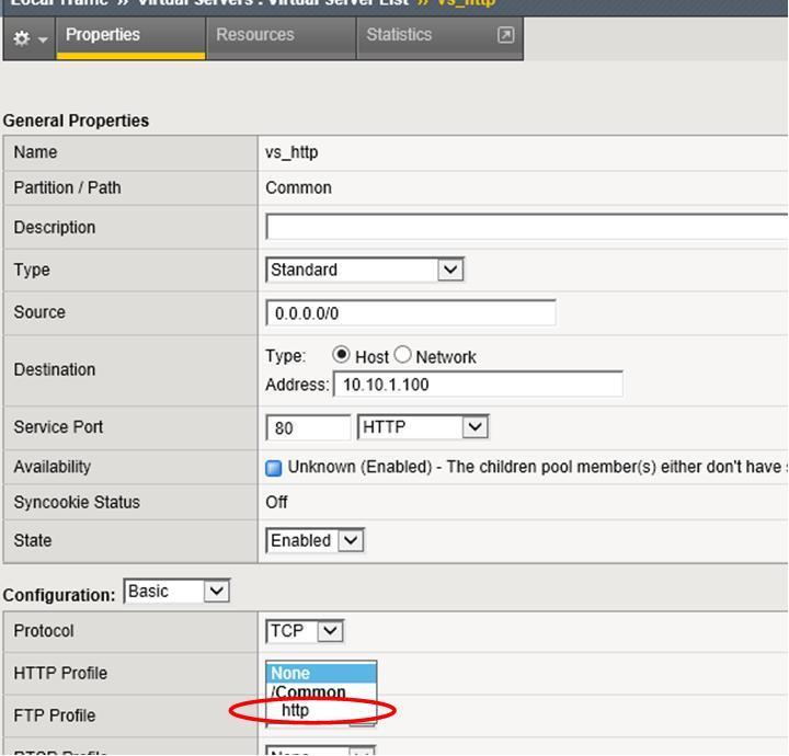
As this feature is obviously on top of the HTTP protocol which is using the TCP protocol. Under the virtual server configuration, when you select the destination port as port 80, it automatically applies the TCP profile. However, the HTTP profile is not by default selected. So if you directly apply the cookie persistence profile (Local traffic > Virtual Server > Resources) without the HTTP profile, it will produce an error.

But sometimes the error message has been overlooked!
So in order to fix this, you need to go back to the Local traffic > Virtual Server > Properties screen.
Under the HTTP profile, need to select one of the HTTP profile, then update.
Then go back to the resources screen, apply the cookie persistence profile.
|
|
June 9, 2014 06:17:51
Posted By Kepler Lam
|
If you haven't read part 1, click here.
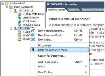
First suspend (or vMotion away) all the VMs running in the ESXi server (if your VSM is running on the ESXi server, remember to save it), put the server to maintenance mode using the vCenter.
Now uninstall the existing VEM by the following command:
/~ # esxcli software vib remove -n cisco-vem-v164-esx
Removal Result
Message: Operation finished successfully.
Reboot Required: false
VIBs Installed:
VIBs Removed: Cisco_bootbank_cisco-vem-v164-esx_4.2.1.2.2.2.0-3.2.1
VIBs Skipped:
If it doesn’t work for some reason, you may need to reboot your ESXi.
Then install the old VEM.
~ # esxcli software vib install -v /vmfs/volumes/Pod2-DataStore/Cisco_bootbank_cisco-vem-v160-esx_4.2.1.2.2.1.0-3.2.1.vib
Installation Result
Message: Operation finished successfully.
Reboot Required: false
VIBs Installed: Cisco_bootbank_cisco-vem-v160-esx_4.2.1.2.2.1.0-3.2.1
VIBs Removed:
VIBs Skipped:
Again, if you are not lucky, it may have some errors or warning, then you may need to reboot your ESXi.
Verify the version and the VEM is running:
~ # vem status
VEM modules are loaded
Switch Name Num Ports Used Ports Configured Ports MTU Uplinks
vSwitch0 1536 5 128 1500 vmnic4
VEM Agent (vemdpa) is running
~ # vem version
Running esx version -1623387 x86_64
VEM Version: 4.2.1.2.2.1.0-3.2.1
VSM Version:
System Version: VMware ESXi 5.5.0 Releasebuild-1623387
After that, back to your vCenter and remember to put your ESXi server to exit the maintenance mode. Then resume (or vMotion back) your VMs.
|
|
June 9, 2014 05:22:08
Posted By Kepler Lam
|
If you are working with the Nexus 1000v, probably you will find that to make sure the version compatibility is a headache.
This blog entry discusses if you have incorrectly installed a newer VEM version which is not compatible with your VSM, then you need to fallback to the old version. The steps are not really so trivial. To upgrade, it is easy. While downgrade is not!
Here I discuss down grade from 4.2.1.2.2.2.0-3.2.1 (fro VSM 4.2.1.SV2.2.2) to 4.2.1.2.2.1.0-3.2.1 (minimal version that support EXSi 5.5 and VSM version 4.2.1.SV2.2.1).
First, verify the existing version:
/vmfs/volumes/98a9ff49-e3284f0c # vem version
Running esx version -1623387 x86_64
VEM Version: 4.2.1.2.2.2.0-3.2.1
VSM Version:
System Version: VMware ESXi 5.5.0 Releasebuild-1623387
/vmfs/volumes/98a9ff49-e3284f0c # esxcli software vib list | head
Name Version Vendor Acceptance Level Install Date
----------------------------- ------------------------------------ ------ ---------------- ------------
cisco-vem-v164-esx 4.2.1.2.2.2.0-3.2.1 Cisco PartnerSupported 2014-05-15
Try directly installing the old version:
/vmfs/volumes/98a9ff49-e3284f0c # esxcli software vib install -v /vmfs/volumes/Pod2-DataStore/Cisco_bootbank_cisco-vem-v160-esx_4.2.1.2.2.1.0-3.2.1.vib
[MaintenanceModeError]
MaintenanceMode is required to remove: [Cisco_bootbank_cisco-vem-v164-esx_4.2.1.2.2.2.0-3.2.1]; install: [].
Please refer to the log file for more details.
Then try installing with the maintenance mode parameter:
~ # esxcli software vib install -v /vmfs/volumes/Pod2-DataStore/Cisco_bootbank_cisco-vem-v160-esx_4.2.1.2.2.1.0-3.2.1.vib --maintenance-mode
Installation Result
Message: Operation finished successfully.
Reboot Required: false
VIBs Installed: Cisco_bootbank_cisco-vem-v160-esx_4.2.1.2.2.1.0-3.2.1
VIBs Removed: Cisco_bootbank_cisco-vem-v164-esx_4.2.1.2.2.2.0-3.2.1
VIBs Skipped:
If you are lucky, you get the above result, then you are done. Unfortunately, for some reason, somtimes the above command won't work. Then you need to use a more complicated aproach. Please follow with my next blog entry.

Taken in my recent trip to deliver the Cisco Nexus 1000v training near the Washington DC area
|
|
April 12, 2014 11:14:34
Posted By Kepler Lam
|
In the discussion of the SECURE course 2 weeks ago, there is a topic about the routing options for DMVPN network. It mentions that If you are using full mesh mode for DMVPN, and using OSPF routing protocol, then you should use OSPF broadcast mode instead of point-to-multipoint mode for the tunnel interface.
The reason is that in DMVPN, spoke site to spoke site tunnel establishment relies on the next hop address to be the spoke site instead of the hub site, see the diagram below:
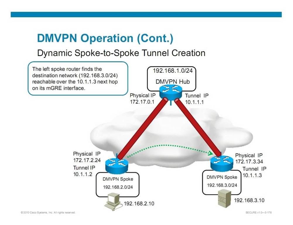
While OSPF broadcast mode satisfies this requirement, see my blog entry on OSPF broadcast and NBMA mode.
Author: Kepler Lam
Certified Cisco System Instructor since 1998
|
|
April 12, 2014 09:52:08
Posted By Kepler Lam
|
Again, I’m teaching Route course this week. Another things that students are interesting to discuss is about the compatibility of different OSPF mode in NBMA network.
I’m not going to discuss how those different mode are being used, as its been discussed in many other website. Those modes are summarized as the following slide:

If you take a look on the above summarized slide, you will find that there are 2 categories: one has DR/BDR selection (for the Broadcast and NBMA mode), while the other category does not have DR/BDR selection (other 3 modes). Actually, that is the boundary of compatibility i.e. the modes in same category are compatible.
Yet, maybe you also know that in order to form neighbors, OSPF routers will require to have consistence hello/dead interval. So even though the modes are compatible, you still need to make sure that the hello/dead interval need to be the same.
Besides, also depending on whether you are using main interface/multipoint/point-2-point subinterfaces, they have different default OSPF mode.
E.g. if you have a hub-and-spoke topology, your hub site uses a multipoint or main interface (which default mode is NBMA). Then for hub site to use OSPF point-2-multipoint mode, you need to explicitly configure. While for the spoke site, even it only has one single PVC to the hub, if you use the main interface instead of a point-2-point subinterface, you still need to define the mode in the main interface as point-2-point mode.
Following is a workable example:
Hub site:
hostname R1
!
interface Loopback0
ip address 10.1.1.1 255.255.255.255
!
interface Serial0/0/0
no ip address
encapsulation frame-relay
!
interface Serial0/0/0.1 multipoint
description Link to R2, R4
ip address 10.1.110.1 255.255.255.0
ip ospf network point-to-multipoint
frame-relay map ip 10.1.110.2 112 broadcast
frame-relay map ip 10.1.110.4 114 broadcast
!
router ospf 1
router-id 1.1.1.1
log-adjacency-changes
network 10.0.0.0 0.255.255.255 area 0
!
Spoke site:
hostname R2
!
interface Loopback0
ip address 10.2.2.2 255.255.255.255
!
interface Serial0/0/0
ip address 10.1.110.2 255.255.255.0
ip ospf network point-to-point
ip ospf hello-interval 30
encapsulation frame-relay
!
router ospf 1
router-id 2.2.2.2
log-adjacency-changes
network 10.0.0.0 0.255.255.255 area 0
!
R1 and R2 can successfully form neighbors and exchange routes:
R1#sh ip ospf neighbor
Neighbor ID Pri State Dead Time Address Interface
2.2.2.2 1 FULL/BDR 00:00:38 10.1.110.2 Serial0/0/0.1
R1#sh ip route
...
10.0.0.0/8 is variably subnetted, 3 subnets, 2 masks
O 10.2.2.2/32 [110/65] via 10.1.110.2, 00:02:49, Serial0/0/0.1
C 10.1.1.1/32 is directly connected, Loopback0
C 10.1.110.0/24 is directly connected, Serial0/0/0.1
Please visit my other blog entry for an exmaple of broadcast and NBMA mode.
|
|
April 12, 2014 09:52:08
Posted By Kepler Lam
|
Although, OSPF broadcast and NMBA mode can also work in a partial mesh network, you need to carefully configure to make it works. There are few things that you need to cater:
- You need to select a site with all PVCs to all other site (e.g. hut site in a hut-and-spoke topology) as the DR and properly tune the priority.
- All sites still need to be directly reachable with each other, so if 2 sites that doesn’t have a PVC between them, then you need to explicitly use a frame-relay map to map the other sites through a PVC to a 3rd site that connects these 2 sites. E.g. spoke sites can reach each other through the hub site. (See the similar discussion for EIGRP NBMA design).
- Sites that use frame-relay map command to reach other site cannot use the broadcast mode, must use NBMA mode and explicitly define other sites as neighbors.
Following is a workable configuration where R1 is the hub site, R2 and R4 are 2 spoke sites that each only has one single PVC to R1.
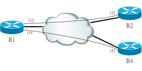
R1:
interface Serial0/0/0.1 multipoint
description Link to R2, R4
ip address 10.1.110.1 255.255.255.0
ip ospf network broadcast
ip ospf priority 10
frame-relay map ip 10.1.110.2 112 broadcast
frame-relay map ip 10.1.110.4 114 broadcast
!
router ospf 1
router-id 1.1.1.1
log-adjacency-changes
network 10.0.0.0 0.255.255.255 area 0
R2:
interface Serial0/0/0
ip address 10.1.110.2 255.255.255.0
encapsulation frame-relay
ip ospf hello-interval 10
frame-relay map ip 10.1.110.4 121 broadcast
R4:
interface Serial0/0/0
ip address 10.1.110.4 255.255.255.0
encapsulation frame-relay
ip ospf hello-interval 10
frame-relay map ip 10.1.110.2 141 broadcast
R2 and R4 can successfully exchange routes:
R2#show ip route
...
10.0.0.0/8 is variably subnetted, 4 subnets, 2 masks
C 10.2.2.2/32 is directly connected, Loopback0
O 10.1.1.1/32 [110/65] via 10.1.110.1, 00:03:54, Serial0/0/0
O 10.4.4.4/32 [110/65] via 10.1.110.4, 00:03:54, Serial0/0/0
C 10.1.110.0/24 is directly connected, Serial0/0/0
R4#show ip route
...
10.0.0.0/8 is variably subnetted, 4 subnets, 2 masks
O 10.2.2.2/32 [110/782] via 10.1.110.2, 00:04:08, Serial0/0/0
O 10.1.1.1/32 [110/782] via 10.1.110.1, 00:04:08, Serial0/0/0
C 10.4.4.4/32 is directly connected, Loopback0
C 10.1.110.0/24 is directly connected, Serial0/0/0
What is the next hop for the route advertised by R4 (10.4.4.4) when received in R2? It accounts why R2 and R4 need to be reachable to each other.
See also DMVPN configuration.
|
|
March 14, 2014 08:54:45
Posted By Kepler Lam
|
This week just finish teaching the ICOMM course, it reminds me a problem that I’ve been facing in a CUCM Active Directory integration project 2 years ago. The problem was after synchronizing the AD, as we have some time lag that some users are not ready in the AD, so those users become inactive in the CUCM.
As there should be a grace period that the CUCM will not immediately remove those users, so they are still in the CUCM’s configuration. However, as those users become inactive, they are not able to login the extension mobility.
Even we disable the AD sync, those users will not automatically change back to active again. Also, in the CUCM admin page, there is no option to reactive them. We tried to call up the TEC support to see if there is any “unofficial” way to reactive them. Yet, we can’t get any answer.
Eventually, I figure out that there is a solution to use the undocumented “run sql” command to directly change the CUCM database.
The following shows the way.
In CUCM, create 2 users that doesn’t exist in the AD before tuning on the AD sync, using the CUCM command line interface, you can use the following command to show the status:
admin:run sql select userid,status from enduser
userid status
============= ======
user2 1
user1 1
Now configure the AD sync and perform the sync once.

After the synchronization completes, these 2 users become inactive:
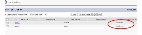
Double check using the CLI, the status also shown to be changed with new value as 2:
admin:run sql select userid,status from enduser
userid status
============= ======
user2 2
user1 2
If I tried to login the EM using one of the user account, you will get an error.
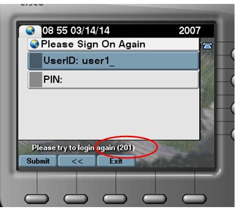
Even disable the AD sync, the user account still in inactive state.
Now using the CLI, execute the following command (optionally, you can add 'where userid="user"' to change a particular user):
admin:run sql update enduser set status=1
Rows: 2
admin:run sql select userid,status from enduser
userid status
============= ======
user2 1
user1 1
Check the status under the CUCM web interface, now they are back.
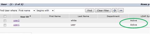
Also, able to login successfully.
|
|
|
|