|
February 14, 2014 10:33:52
Posted By Kepler Lam
|
Though actually this simple topic is covered in CCNA, as this week just finish the teaching of CCNA, I still find that this really deserve to discuss.
The problem is about the VLAN configuration. In the new CCNA course, there is a lab about the inter-vlan router using the following topology:
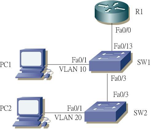
Objective of the lab is quite simple, just use the Router to do inter-vlan routing. PC1 will be put on VLAN 10, while PC2 will be put on VLAN 20.
Now in SW1, create VLAN 10, configure port 0/1 to be VLAN 10. While port 0/3 and 0/13 need to be configured as trunk and allow VLAN 10,20 traffic. Configuration as below:
hostname SW1
!
vlan 10
!
interf FastEthernet 0/1
switchport mode access
switchport access vlan 10
no shutdown
!
interf FastEthernet 0/3
switchport mode trunk
switchport trunk allowed vlan 1,10,20
no shutdown
!
interf FastEthernet 0/13
switchport mode trunk
switchport trunk allowed vlan 1,10,20
no shutdown
Similarly, in SW2, create VLAN 20, configure port 0/1 to be VLAN 20. While port 0/3 to be trunk, also allow VLAN 10,20 traffic. Configuration as below:
hostname SW2
!
vlan 20
!
interf FastEthernet 0/1
switchport access vlan 20
no shutdown
!
interf FastEthernet 0/3
switchport mode trunk
switchport trunk allowed vlan 1,10,20
no shutdown
!
Now go to the Router, create 2 subinterfaces in interface 0/0 with VLAN 10 and 20 respectively. Configure the corresponding IP addresses - VLAN 10 uses subnet 10.1.10.0/24, while VLAN 20 uses subnet 10.1.20.0/24.
interface GigabitEthernet 0/0
no shutdown
description Link to LAN Switch
ip address 10.1.1.1 255.255.255.0
!
interface GigabitEthernet 0/0.10
encapsulation dot1q 10
ip address 10.1.10.1 255.255.255.0
!
interface GigabitEthernet 0/0.20
encapsulation dot1q 20
ip address 10.1.20.1 255.255.255.0
!
Finally, for PC1 configure the corresponding IP address and default gateway as follows:
IP: 10.1.10.100 255.255.255.0
default gateway: 10.1.10.1
Similarly for PC2:
IP: 10.1.20.100 255.255.255.0
default gateway 10.1.20.1
OK, everything is ready? Should be able to ping between the PC1 and PC2.
Wait a miunte, lets first try to ping the default GW. In PC1, ping 10.1.10.1, perfectly works.
In PC2, ping 10.1.20.1. Hooops? Timeout!
So whats missing here? You may already able to figure it out. Problem is in SW1. It misses the VLAN 20. Though it doesn't has any access port on VLAN 20, it still needs to pass VLAN 20 traffic. Without the VLAN 20 definition, in fact, it won't carry VLAN 20 traffic on the trunk between it and the router. Thus VLAN 20 traffic is dropped and won't send to router.
To fix it:
sw1(config)# vlan 20
|
|
February 3, 2014 09:30:30
Posted By Kepler Lam
|
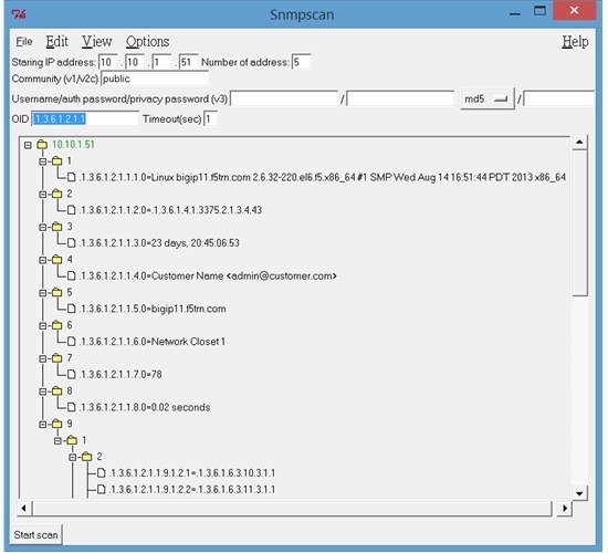
Recently, I have tested the F5 (Big IP) LTM v11.4 SNMP configuration and my snmpscan tools. Here is the steps.
1. In the F5 LTM admin webpage, select the SNMP->Agent->Configuration

2. In the configuration page, need to add your SNMP management software subnet (or starting octets).

3. Then go to the "access (v1,v2c)" screen (of course can use v3). Create a new access.

4. In the access creation screen, you define the community string. Yet, what I want to point out is that if you want to restrict the OID branch that this community allows, first the OID syntax begins with a dot. E.g. for MIB-2, enter ".1.3.6.1.2.1". Secondly, need to select the source IP that allow access.

5. Now, you can download my free snmpscan tools under IPtools. Enter the IP of your F5, comunity and OID. Click the start scan, now you get the values of the MIB tree branch as below:
|
|
January 14, 2014 10:47:40
Posted By Kepler Lam
|
This week, I am teaching an old class Route, and just want to sum up some of my old notes about some erratic of the course material.
In the discussion of running EIGRP over NMBA (e.g. Frame Relay) network, there is a slide as below:

What's wrong with this slide (at least some pitfall)? This slide seems want to show in the case of partial mesh Frame Relay subscription, it can still work with EIGRP by configurating the IP address in main interface without using subinterface.
In fact, that’s not true. In order to make the above work, there are few things that need to cater.
- As R2 and R3 do not have a direct PVC between them, in order to make them able to communicate with each other, there must be an explicit "frame-relay map" configuration to map the remote IP to the local DLCI. Yet, wait a minute, as there is no PVC between them, so what DLCI to use? Acutally, you need to map the remote IP to the DLCI number to R1 (middle router).
- As now, R2 and R3 actually reach each other by using R1, its obvious that the interface of R1 must be up.
- Even if R2 and R3 can reach each other, it doesn’t necessary means that they can form EIGRP neighbor. In such case, you need to explicitly use the "neighbor <remote IP> <outgoing interface>" statement to manually configure EIGRP neighbor.
- But once you use the neighbor statement, the multicast method for automatic neighbor discovery will no longer work. That means, you not only need to manually configure neighbor between R2 and R3, you also need to manually configure R1 as neighbor.
- If you still want to use multicast neighbor, another method it to just let R2 and R3 forming neighbor with R1 only, without letting them to form neighbor of each other. In such case, you still need to disable split horizon for eigrp in R1 by using “no ip split-horizon eigrp <AS>” command , otherwise R2 can’t learn route from R3 (and vice versa), even thought R2 and R3 still can’t form neighbor. R2 will be able to learn route of R3 (and vice versa), next hop will become R1. You can even skip the frame-relay map (but R2 cannot directly reach R3). Following is the configuration of this method:
For R1:
hostname R1
interface Serial0/0/0
ip address 10.1.110.1 255.255.255.0
encapsulation frame-relay
no ip split-horizon eigrp 1
router eigrp 1
network 10.0.0.0
For R2:
hostname R2
interface Serial0/0/0
ip address 10.1.110.2 255.255.255.0
encapsulation frame-relay
frame-relay map ip 10.1.110.3 221
router eigrp 1
network 10.0.0.0
For R3:
hostname R3
interface Loopback1
ip address 10.1.3.1 255.255.255.0
interface Serial0/0/0
ip address 10.1.110.3 255.255.255.0
encapsulation frame-relay
frame-relay map ip 10.1.110.2 231
router eigrp 1
network 10.0.0.0
Now if you show the routing table of R2: R2#sh ip route
...
10.0.0.0/24 is subnetted, 2 subnets
D 10.1.3.0 [90/21152000] via 10.1.110.1, 00:07:34, Serial0/0/0
C 10.1.110.0 is directly connected, Serial0/0/0
What's the next hop of the route (10.1.3.0) advertised by R3?
|
|
January 7, 2014 06:39:27
Posted By Kepler Lam
|
Just finish the FlexPod training, there are 2 things that want to clarify.
The fist thing is about the FCoE connectivity between the Nexus 5K and the Netapp storage. The reference architecture (diagram below) shows that a vPC is formed between the 2 N5K, then the vPC connects to the ifgrp of the Netapp filer.

Here there is an important points to be aware. The vPC can be used to carry traffics for all data VLANs, but not the FCoE traffic. In fact, in the design guide, it mentions that in order to key the SAN A/B design (as from the UCS SAN traffic design, we always keep 2 different storage paths). the FCoE traffic of a particular VSAN (which actuatlly caried by VLAN) will not be send in both links of the vPC. E.g. if the left hand side N5K is carrying the traffic of VSAN 201 over VLAN 101, while the right hand side VSAN 202 over VLAN 102 Then the links from the left hand side N5K to the Netapp will only carry VSAN 201/VLAN 101, while right hand side is VSAN 202/VLAN 102.
While data VLAN will have no restriction, e.g. if VLAN 50 is for data, then the VLAN 50 traffic can be carried over all 4 links (as below).
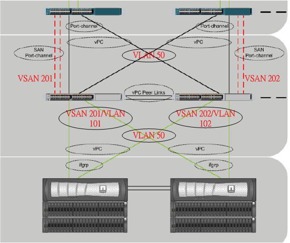
The 2nd thing is, currrently the FCoE cannot support FCoE port channel, i.e. you can't use 2 parallel links connecting the Netapp filer to the same N5K. Thus for FCoE storage deployment, the reference design is the only valid physical connectivity design.
|
|
December 21, 2013 09:52:57
Posted By Kepler Lam
|
Just finish teaching the Cisco UCS (DCUCI) course this week, I find that there is a small bug about the Unified port configuration and want to share in this blog entry.
As in the lab, it requires to configure last few ports of the Fabric Interconnect as FC uplink ports, while we are using the 6248 Fabric Interconnect, which by default the ports are unified ports, so need to first configure them as the FC ports.
The ports to be configured are all the ports in the expansion slot. By using the UCSM, select the corresponding Fabric Interconnect, and click the Configured Unified Ports:
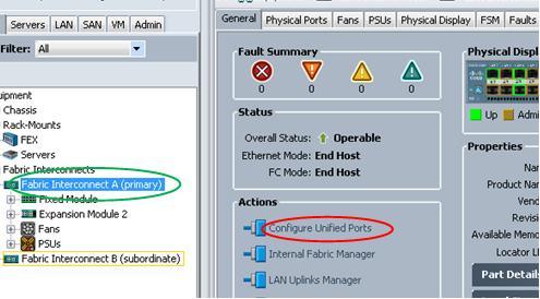
In the popup window, select the Configure Expansion Module Ports:
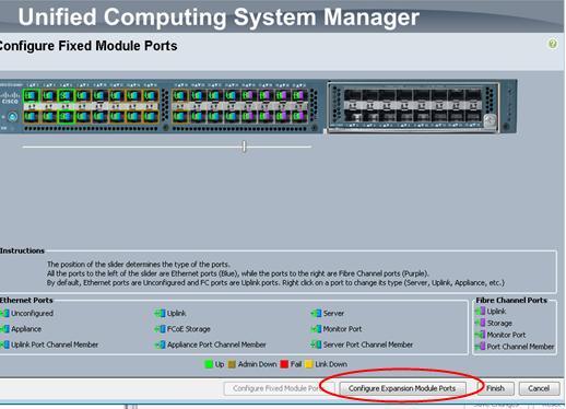
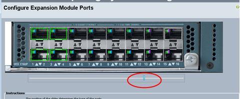
Drag the slide bar, so that the right hand side ports will become FC ports. Then click Finish.
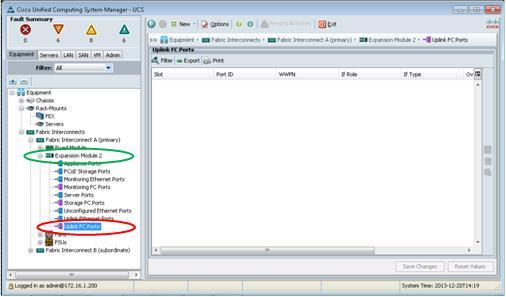
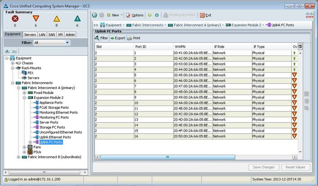
What happen is that you would expect that those configured ports should be appeared under the Uplink FC port, however nothing is found there!
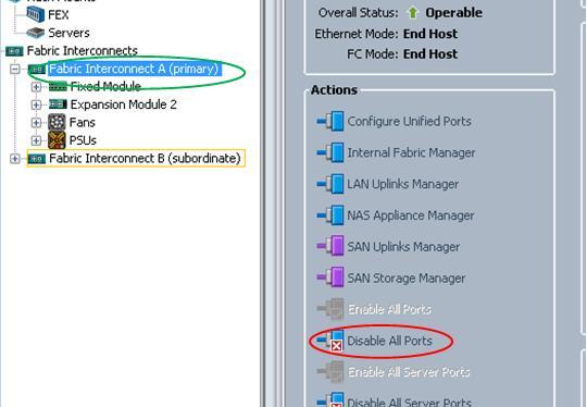
So how can you fix it, you need to Disable All Ports:
Then re-enable all the ports again:
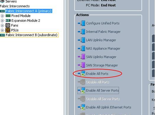
Now all the FC uplink ports appear:
- Kepler (Cisco Certified System Instructor #20388, since 1998)
|
|
December 15, 2013 08:37:07
Posted By Kepler Lam
|
When teaching the Cisco Firewall (ASA) course last week, there is a question about the port chnanel and failover policy. As for the failover policy, you can specify how many monitored interface fail will trigger the failover (default is one). The question is if port channel is being used, then will it treated as one single interface or as number of underlying physical interface.
Though not actually tested out, by using the ASDM wizard to setup failover, there is a screen to select the interface being monitored.
If you have created a port channel, you can only select the port channel interface to be monitored instead of the underlying physical interfaces, see figures below:
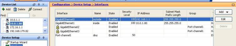
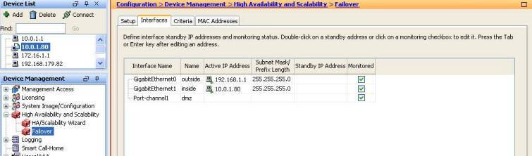
That means, from the failover policy of view, it will just count the port channel interface as one single interface disregarding how many underlying physical interfaces it consists of.
|
|
December 13, 2013 10:56:07
Posted By Kepler Lam
|
When teaching the H3CNE class, one of the questions is about the compatibility of the HDLC encapsulation of H3C router with Cisco router. As Cisco HDLC is well known to be a propriety implementation, while H3C doesn’t state clearly about its implementation.
So what’s the answer? Maybe you want to try it out by yourself. You don’t need to have the actual device, you can use the H3C simulator (LITO) and Cisco simulator (GNS3) to test it out. If you don’t know where to download it, please visit my other Blog entry.
Now, how to emulate the serial connection between GNS3 and LITO, as both of them support the using of UDP session to emulate the serial connection, however the underlying implementation is different, so you can’t directly connect them together. Instead you can use the UBridge tool to bridge them. Following diagram illustrates the connection.
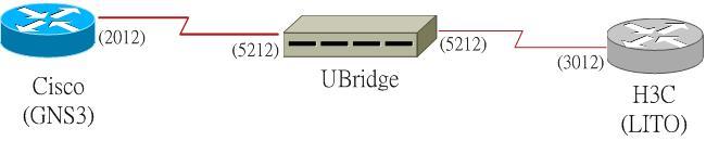
You need to create 2 different UDP sessions: one session between the Cisco Router to the UDP Bridge, the other between the H3C Router to the UDP Bridge.
So you require2 pairs of UDP port numbers, e.g. Cisco serial interface use 2012, UBridge to Cisco use 5212, H3C interface use 3012, UBridge to H3C use 5312.
LITO configuration under the “hardcfg.tcl”:
AddSerial -slot 1 -local 127.0.0.1 -lport 3012 -dest 10.1.1.2 -dport 5312
GNS3 configuration (please consult the GNS document): udp:"2011:10.1.1.2:5211"
While for the UBridge, you need to create 2 legs and put them into a group, you can choose any group number. E.g. group 3. Now you can start the UBridge as follows:
c:\iptools>ubdg 3#C:S@5212:127.0.0.1:2012 3#H:S@5312:127.0.0.1:3012
In the H3C router console, configure the serial link use hdlc encapsulation. E.g.:
[R1]interface Serial0/1/2
[R1-Serial0/1/2]link-protocol hdlc
In the Cisco end, just “no shutdown” the interface, (as Cisco by default use) . then both H3C and Cisco’s interface will become up.
Now, you get the answer.
|
|
November 28, 2013 10:10:30
Posted By Kepler Lam
|
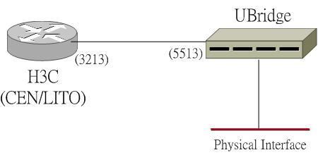
Once again, if for some reason you cannot bring up the LITO GUI (like my new laptop running Windows 8 – another garb**** after vista!!!), or if you don’t want to use the GUI. There is another way to connect the H3C simulator to the VPC.
What you need to do is to use the UBridge tools to bridge the LITO and the VPC as shown in the diagram below:

You need 2 pairs of UDP port #, 1 pair between LITO and UBridge, the other between VPC and UBridge.
H3C configuration under the “hardcfg.tcl”:
AddEthNew -speed 1000 Level3 -canswitch -slot 0 -subslot 0 -local 127.0.0.1 -lport 19002 -dest 127.0.0.1 -dport 30001
VPC configuration:
VPCS[1]> set lport 20000
VPCS[1]> set rport 30000
While for the UBridge, you need to create 2 legs and put into one group (e.g. use group # 1),
VPC leg: 1#C:E@30000:127.0.0.1:20000
H3C Leg: 1#H:E@30001:10.1.1.3:19002
so execute:
C:\iptools>ubdg.bat 1#H:E@30001:127.0.0.1:19002 1#C:E@30000:127.0.0.1:20000
Now your H3C router should be able to reach the VPC.
- Kepler
|
|
November 23, 2013 10:19:28
Posted By Kepler Lam
|
As discussed in my other Blog entry that the H3C simulator LITO/CEN is not compatible with Winpcap 4.0 (though LITO actually can run without Winpcap, yet it cannot bridge to physical interface). Now with the new release of my open source tool UBridge, you can bridge LITO’s Ethernet interface with the Windows local interface (you still need Winpcap 4.x). Like the following diagram:
Please refer to the iptools project page for free download.
|
|
November 23, 2013 10:13:37
Posted By Kepler Lam
|
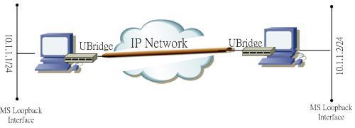
With the new release of my open source tool UBridge (inside the iptools 0.3.0 package), it supports a new feature Ethernet over UDP (EoUDP). What’s the usage of it? There can be many applications, one of them is to use it as a light weight VPN tunnel to bridge the loopback interfaces of your Windows PC to form layer 2 adjacency.
For example. if you have two Windows machine in 2 different subnet, but for some recent, you need to put them into same subnet to do some testing. However, you are not able to change your network setting. Then the UBridge program can help you. You can bridge the MS loopback interfaces of the 2 PCs and put them in same subnet, as shown in the diagram below.
If you are using VMware workstation, another usage is to bridge the VMs inside your Windows PC to the VMs of another PC, like the diagram below: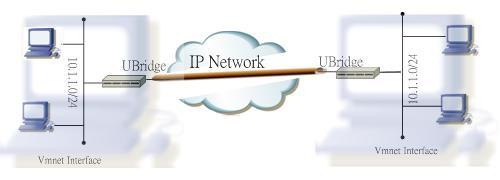
Please visit the project website for detail configuration and download information.
|
|
|
|